 Sign-up for free online course on ANSYS simulations!
...
The first two thing we check for verification are the mass conservation and inlet boundary conditions. We check the inlet boundary conditions to ensure that the UDF is doing what we expected it to performconditions are as we expect. Then, we do a mesh refinement and use a smaller time-step to check whether the results are consistent with the original calculation. By using a finer mesh and a smaller time-step, we investigate the effects of truncation error caused by spatial discretization and temporal discretization. Then we will do a case comparison for the results obtained after spatial and temporal refinement.
...
To check whether mass is conserved in this calculation, open up solutions. Go go back into Fluent and go to Reports -> → Fluxes and then under options, check "Mass flow rate". Then select the one inlet and two outlets. We would expect the mass flux to sum up to zero (or extremely small).

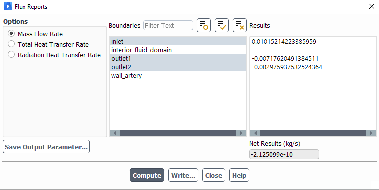
As we can see from the window above, the mass fluxes add up to -2.624226e125e-0710, which is very close to zero. Thus, we can conclude that mass is conserved in the simulation.
Under construction
Mesh Refinement & Smaller
...
In the original calculation, the time-step that was used was 0.01s. For verification, a smaller time-step of 0.005s is used.
Case Comparison
...
Pseudo-timestep
Under construction
Validation
It is also always good to compare the results obtained from simulations with experimental results. In this case however, we do not have experimental data but we do have description of flow in the carotid artery, courtesy of your textbook. We find that the flow in the internal and external carotid arteries should be approximately 70% and 30% of the total flow in the common carotid artery. We can check this in Fluent by using the mass flow rate values we found earlier.
...
Validation
In this blood flow in 3D bifurcating artery simulation, we have included most of the physical properties in this problem, such as non-newtonian fluid properties and pulsatile flow. However, in order to perform a simulation closer to the real scenario, elastic wall features should be included. This can be done by coupling the solution from FEA simulation and CFD simulation in ANSYS workbench. It is also always good to compare the results obtained from simulations with experimental results. In this case however, we do not have experimental data based on the exact same geometry.
References:
[1] Cutnell, John & Johnson, Kenneth. Physics, Fourth Edition. Wiley, 1998: 308.
[2] Siebert, Mark W. & Fodor, Petru S. Newtonian and Non-Newtonian Blood Flow over a Backward- Facing Step – A Case Study. Excerpt from the Proceedings of the COMSOL Conference 2009 Boston 2009.
[3] SINNOTT, Matthew. CLEARY, Paul W. & PRAKASH, Mahesh. An investigation of pulsatile blood flow in a bifurcating artery using a grid-free method. Fifth International Conference on CFD in the Process Industries CSIRO, Melbourne, Australia 2006
...