 Sign-up for free online course on ANSYS simulations!
...
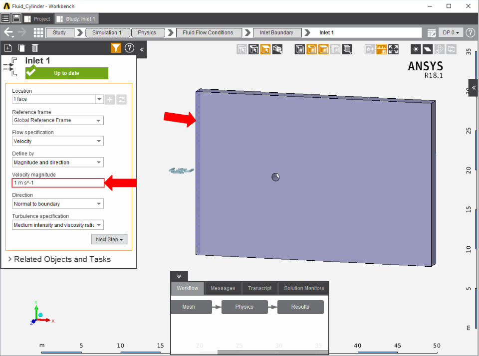
First, the inlet must be defined using the Fluid Flow Conditions. In the Add drop down menu by Fluid Flow Conditions, select Inlet. Then, using the Face selection tool, define an inlet at the end closest to the cylinder. Make sure to input the Velocity magnitude as 1 m/s.
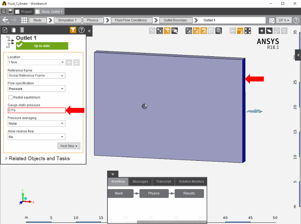
Once the inlet is defined, the outlet is next. In the same menu, use the Outlet condition to define an outlet at the end of the enclosure farthest from the cylinder. Assign a Gauge static pressure of 0 psi.
Add a Symmetry condition from the Add drop down menu to the side faces of the flow volume.

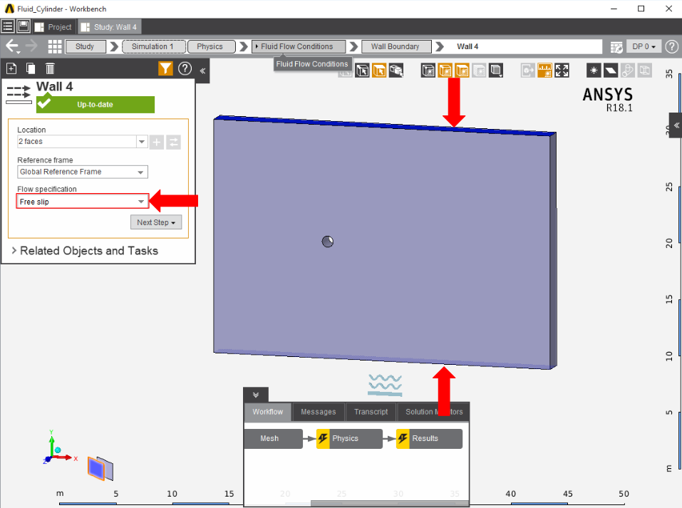
A free slip wall condition must be created in order to channel the air inside of the enclosure, much like one would find in a wind tunnel. Select the Wall condition from the Add drop down menu and apply it to the top and bottom of the enclosure, then change the Option under Flow Specification to Free slip.
Next, a Wall condition must be added to all surfaces that are not already defined. Most of the time, AIM will automatically create the walls once the option is selected; AIM selects every face that doesn't already have a constraint on it.

...