 Sign-up for free online course on ANSYS simulations!
...
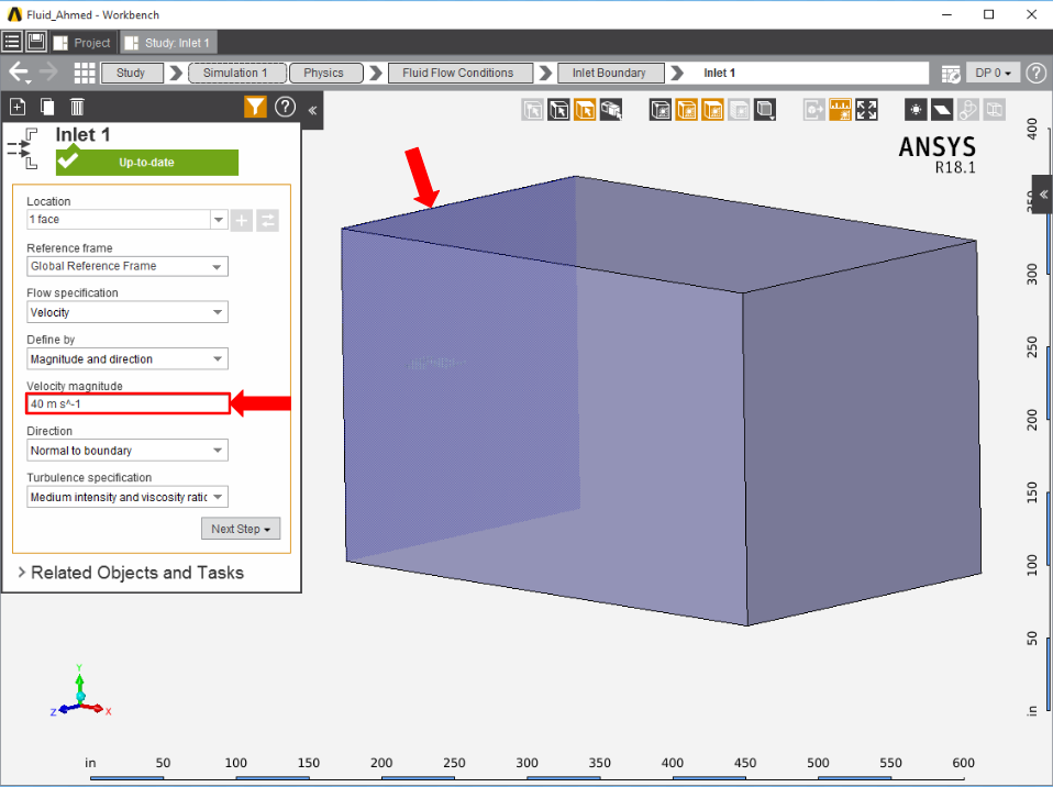
First, the inlet must be defined using the Fluid Flow Conditions. In the Add drop down menu by Fluid Flow Conditions, select Inlet. Then, using the face selection tool, define an Inlet at the face upstream of the Ahmed body. The front of the body is the taller end with the rounded edges and corners. Make sure to input the Velocity magnitude as 40 m/s.
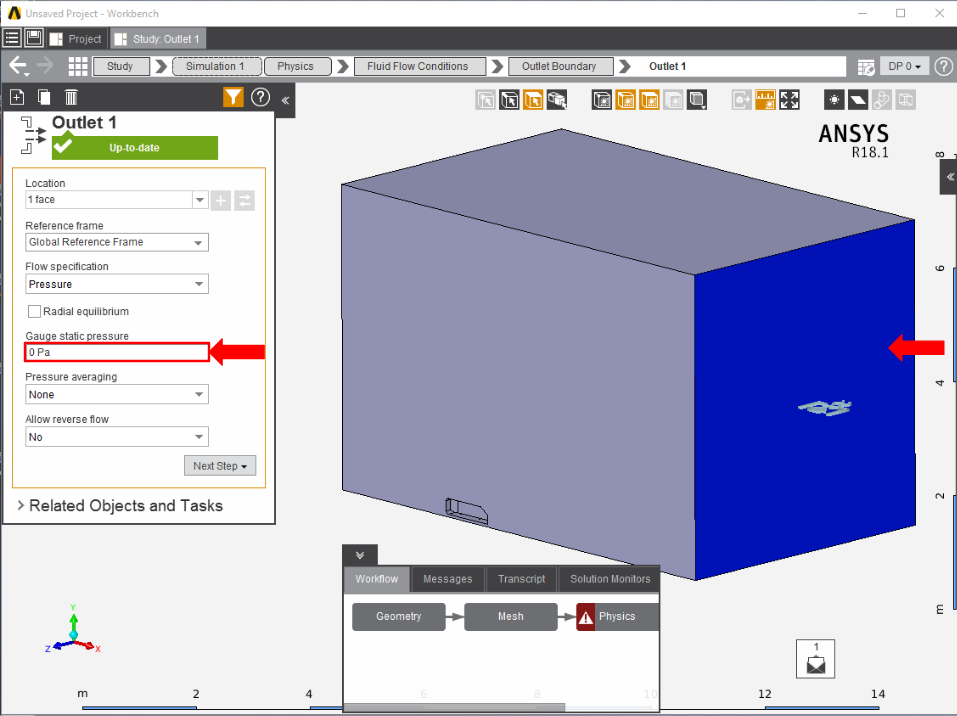
Once the inlet is defined, the outlet is next. In the same Add menu, use the Outlet condition to define an outlet downstream of the body. Assign a Gauge static pressure of 0 psi.
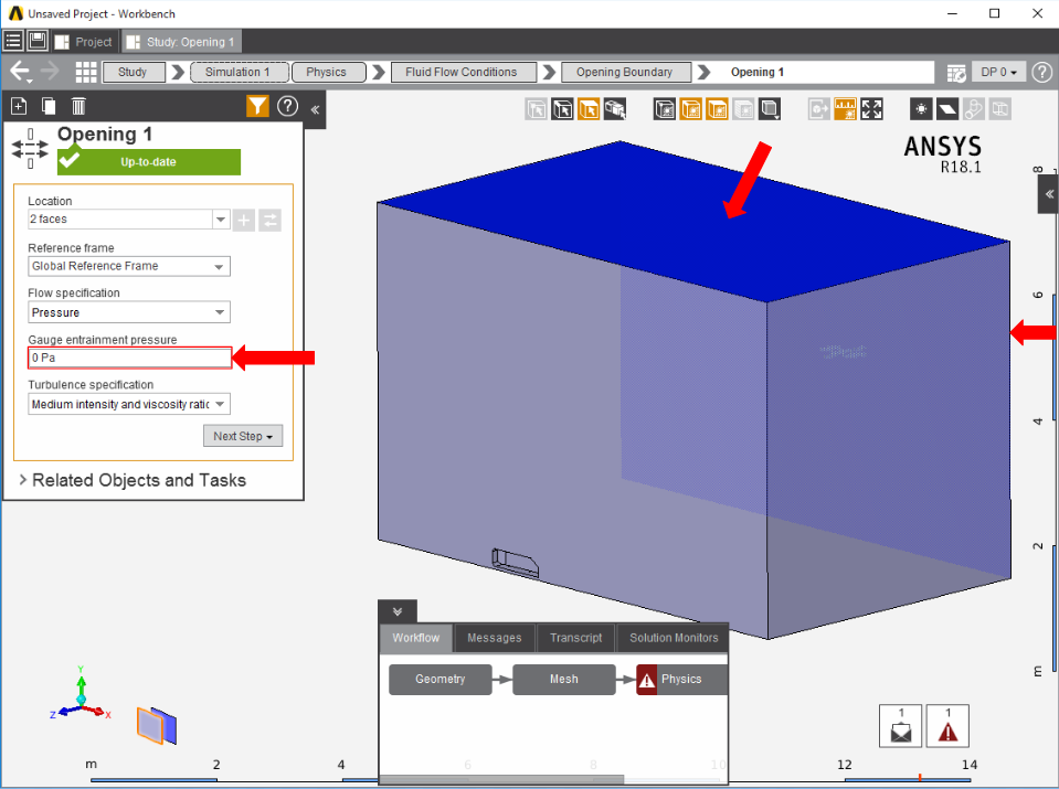
Create openings for the sides of the flow volume by selecting Opening in the Add drop down menu. Select the top face of the flow volume, and the side face away from the Ahmed body, then input 0 Pa for the Gauge entrainment pressure.
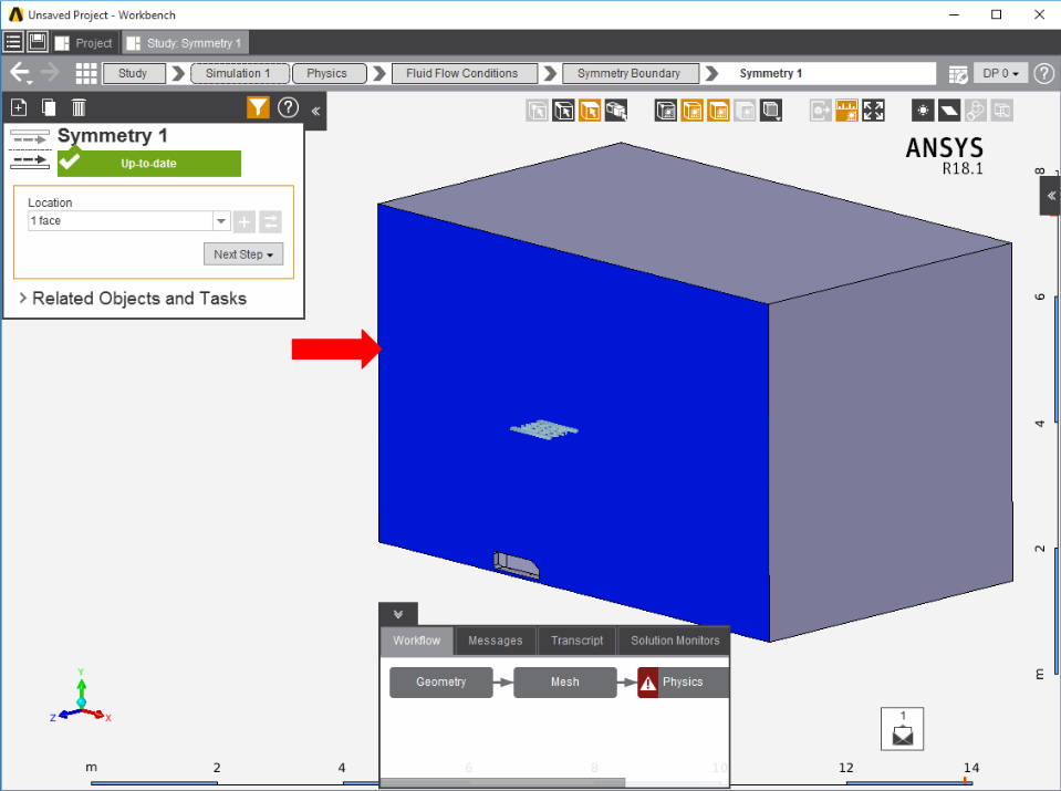
Add a Symmetry condition from the Add drop down menu to the face of the flow volume which passes through the Ahmed body.
A Wall condition needs to be added for the remaining faces of the flow volume. In the Add menu, select Wall. AIM will automatically select all faces not already assigned.

Press Solve Physics in the Physics panel to run the calculations, then move on to the next step.
...