 Sign-up for free online course on ANSYS simulations!
...
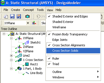
In order to make sure that the cross section was assigned to the solid body click on "View", then click on "Cross Section Solids" as shown below.
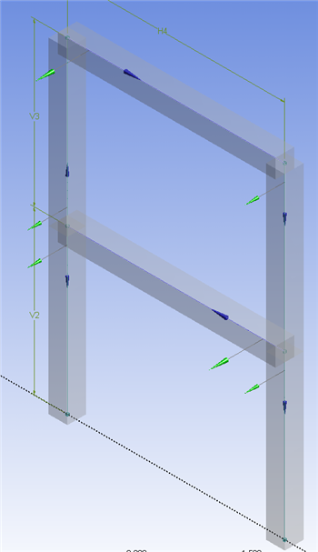
Then click on the little turquoise dot,  , located by the axes in the bottom right portion of the screen. You should now see the the plane frame rendered in 3D as shown below. Don't be misled by this graphical rendering; our model consists only of lines representing the mid-lines of each frame member.
You can close the Design Modeler and you may want to save your project.
...
Transfer "Line Bodies" to Mesher
Note: This step needs to be done only in version 13.0. It can be skipped in version 14.0 and later.
...