 Sign-up for free online course on ANSYS simulations!
| Include Page | ||||
|---|---|---|---|---|
|
| Include Page | ||||
|---|---|---|---|---|
|
...
In order to assess the numerical accuracy of the results obtained, it is necessary to compare results on different meshes. We'll re-do the calculation on a 100x60 mesh which has twice the number of nodes in the radial direction as the 100x30 mesh.
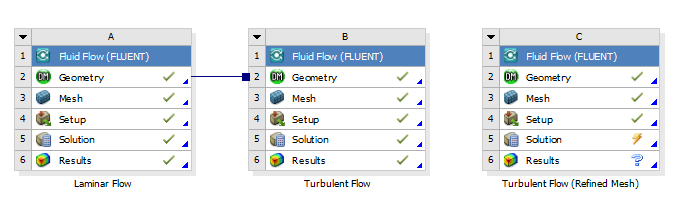
In Workbench, under Turbulent Flow project, right click on Fluid Flow (FLUENT) and click duplicate. Rename the duplicate project to Turbulent Flow Refined Mesh. You should have three project cells in workbench.
Double click on Mesh for Turbulent Flow Refined Mesh. The ANSYS Mesher window will open. Under Outline, expand mesh tree and click on Edge Sizing 2.
Highlight "Edge Sizing 2". Under Details of "Edge Sizing 2", increase Number of Divisions to 60. This will refine the mesh in the radial direction at the inlet.
Highlight "Edge Sizing 3". Under Details of "Edge Sizing 3", increase Number of Divisions to 60. This will refine the mesh in the radial direction at the outlet.
Click Update to generate the new mesh.
Close the ANSYS Mesher and go back to Workbench windows. Under Turbulent Flow Refined Mesh, right click on Fluid Flow (FLUENT) and click Update. Wait for a few minutes for FLUENT to obtain a solution and update all the results.
We would want to compare the solution on the two meshes. To do that, drag the Solution cell of Turbulent Flow Refined Mesh to Results cell of Turbulent Flow.
Double click the Results cell of Turbulent Flow, and after CFD Post opens, we can compare our results by simply selecting the desired chart!
...