 Sign-up for free online course on ANSYS simulations!
...
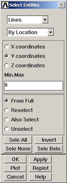
Select Entities menu: Select Lines from the pull-down menu at the top. Select below that. Choose By LocationY coordinates. Under Min,Max, enter 0. This will select all lines whose centers lie at y=0. Make sure From Full is selected so that we are selecting entities from the full model. Click Apply.
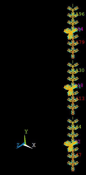
Check which lines have been selected: Select Entities menu >Plot. You should see that the edges along AH have been selected.
...
Select the entire model: Click Select All and then Replot in the Select Entities menu. You should see the S symbol along the edges where the symmetry BC has been applied.
...
We'll first select all edges along AJ. Go back to Select Entities menu: Leave Lines and By Location in place. Choose X coordinates. Under Min,Max, retain 0. This will select all lines whose centers lie at x=0. Make sure From Full is selected. Click Apply.
Check which lines have been selected: Select Entities menu > Replot. You should see that only the edges along AJ are currently selected.
...
Select the entire model: Click Select All and then Replot in the Select Entities menu.
...
Select Entities menu: Leave Lines, By Location and X coordinates selections in place. Under Min,Max, enter W1. This will select all lines whose centers lie at x=W1. Make sure From Full is selected. Click Apply.
Select Entities menu > Replot
...
The (cluttered) display will show that all six DOF's have been constrained.
Select Entities menu: Select All and Replot
Apply Clamped BC along JI
Select Entities menu: Leave Lines, and By Location in place. Choose Y coordinates. Under Min,Max, enter L1. This will select all lines whose centers lie at y=L1. Make sure From Full is selected. Click Apply.
Select Entities menu > Replot
Constrain all six nodal degrees of freedom (DOF) for selected edges:Main Menu > Preprocessor > Loads > Define Loads > Apply > Structural > Displacement > On Lines > Pick All > All DOF > OK
Select Entities menu: Select All and Replot
Save: Toolbar > SAVE_DB
Apply Pressure on Plate
...
Choose areas corresponding to the plate: In the Select Entities menu, select Areas from the pull-down menu at the top. Leave By Location below that. Choose Z coordinates Under Min,Max, enter 0. This will select all areas whose centers lie at z=0. Make sure From Full is selected. Click Apply.
Check which areas are currently selected: Select Entities menu > Replot
Apply a pressure of 0.05 N/mm2 on the plate in the +z direction: Main Menu > Preprocessor > Loads > Define Loads > Apply > Structural > Pressure > On Areas > Pick All
For VALUE, enter 0.05. Click OK.
ANSYS will mark the faces where the pressure is applied. Let's instead plot the applied pressure using arrows to check its direction: Utility Menu > PlotCtrls > Symbols. For Surface Load Symbols, select Pressures and under Show pres and convect as, select Arrows. Click OK. Are the pressures acting in the right direction?
Select Entities menu: Select All, Replot and Cancel. You should now see the entire model. Review that all the BC's have been applied correctly.
...
Utility Menu > File > Write DB log file
Under Write Database Log to, enter the filename for the logfile: shell_step6.lgw. At the bottom of this menu, select Write Essential Commands only. Click OK. Review shell_step6.lgw by opening it in a text editor.
...