 Sign-up for free online course on ANSYS simulations!
| Include Page | ||||
|---|---|---|---|---|
|
| Include Page | ||||
|---|---|---|---|---|
|
Mesh
Open the Mesher
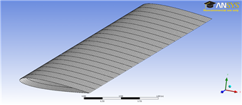
To open the mesher, double click the Model box  in the Project Outline window. This will load ANSYS Mechanical. You should now be able to see the airfoil geometry.
...
The first thing we are going to need to do when the mesher opens is specify the thickness of the airfoil walls. In the Outline window, expand Geometry and select Surface Body. In the Details window, change the thickness to 0.01 m. We also need to specify the material. In the Outline window. In the Details window, select Material > Assignment > Al 6061-T6. The material has now been specified.
Mapped Face Meshing
To apply a mapped face meshing, first click on Mesh in the Outline window. This will bring up the Meshing Menu Bar at the top of the screen. Next, select Mesh Control > Mapped Face Meshing. Select the 2 faces of the mesh by holding down the left mouse button and dragging over the entire geometry. In the Details window, click Geometry > Apply - it should say 2 faces are selected.
Edge Sizing
In the Meshing Menu, click Meshing Control > Sizing. Click the edge selection filter  . Select the 4 curved edges on the outside of the geometry that make up the shape of the NACA 0012 Airfoil as the picture shows:
...
Again, in the Details window change the settings such that Type > Number of Divisions and Behavior > Hard. This time, change the Number of Divisions to 20. Generate the mesh by selecting Mesh > Generate Mesh.
Go to Step 4 - : Physics Setup(Physics)
Go to all ANSYS Learning Modules
See and rate the complete Learning Module