 Sign-up for free online course on ANSYS simulations!
...
| Wiki Markup |
|---|
{alias:shell}
{panel}
|
| Panel |
Author: Rajesh Bhaskaran, CornellUniversityProblem Specification 1. University {color:#ff0000}{*}Problem Specification{*}{color} [1. Start-up and preliminary set-up |ANSYS - Semi-monocoque shell - Step 1]\\ [2. Specify element type andconstants 3. Specify material properties 4. Specify geometry 5. Mesh geometry 6. Specify boundary conditions 7. Solve! 8. Postprocess the results 9. Validate the results |
Problem Specification
In this tutorial, we'll analyze the plane shell with stiffeners shown in the figure below.
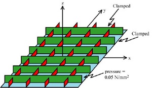
All edges are clamped. A constant pressure of 0.05 N/mm2acts on the underside of the shell (i.e. the pressure acts in the +z direction). Since the geometry and loads are symmetric about both the x and y-axes, we need to model only one-quarter of the structure. The dimensions of the plate and stiffeners are shown in the figure below which shows only one-quarter of the structure.

The Young's modulus E =7.3x10⁴ MPa and the Poisson ratio is 0.33.
Print out this page and have it on hand so that you can easily refer to the geometry and problem specification as you go through the tutorial.
Go to Step 1: Start-up and preliminary set-up
See and rate the complete Learning Module
 constants|ANSYS - Semi-monocoque shell - Step 2]\\
[3. Specify material properties|ANSYS - Semi-monocoque shell - Step 3]\\
[4. Specify geometry|ANSYS - Semi-monocoque shell - Step 4]\\
[5. Mesh geometry|ANSYS - Semi-monocoque shell - Step 5]\\
[6. Specify boundary conditions|ANSYS - Semi-monocoque shell - Step 6] \\
[7. Solve\!|ANSYS - Semi-monocoque shell - Step 7] \\
[8. Postprocess the results|ANSYS - Semi-monocoque shell - Step 8]\\
[9. Validate the results|ANSYS - Semi-monocoque shell - Step 9]
{panel}

h2. Problem Specification

In this tutorial, we'll analyze the plane shell with stiffeners shown in the figure below.
!geometry1.jpg!

([Click for enlarged figure|ANSYS - Semi-monocoque shell - Problem Specification^geometry1_big.jpg].)

All edges are clamped. A constant pressure of 0.05 N/mm{^}2{^}acts on the underside of the shell (i.e. the pressure acts in the \+z direction). Since the geometry and loads are symmetric about both the _x_ and _y_\-axes, we need to model only one-quarter of the structure. The dimensions of the plate and stiffeners are shown in the figure below which shows only one-quarter of the structure.

!geometry2.jpg!

The Young's modulus E =7.3x10{^}4^ MPa and the Poisson ratio is 0.33.
Print out this page and have it on hand so that you can easily refer to the geometry and problem specification as you go through the tutorial. \\
Go to [Step 1: Start-up and preliminary set-up|ANSYS - Semi-monocoque shell - Step 1]

[See and rate the complete Learning Module|ANSYS - Semi-monocoque Shell]

[Go to all ANSYS Learning Modules|ANSYS Learning Modules] |