Sign-up for free online course on ANSYS simulations!
| Include Page | ||||
|---|---|---|---|---|
|
...
| Include Page |
|---|
...
Author: Brandon Kovarovic, Cornell University
Problem Specification
1. Pre-Analysis & Start-Up
2. Geometry
3. Mesh
4. Setup (Physics)
5. Solution
6. Results
7. Verification & Validation
|
Geometry
First open MIMICs and the home screen will appear below.

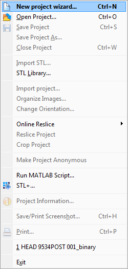
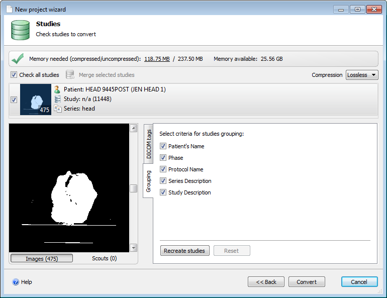
Next select File -> New Project Wizard

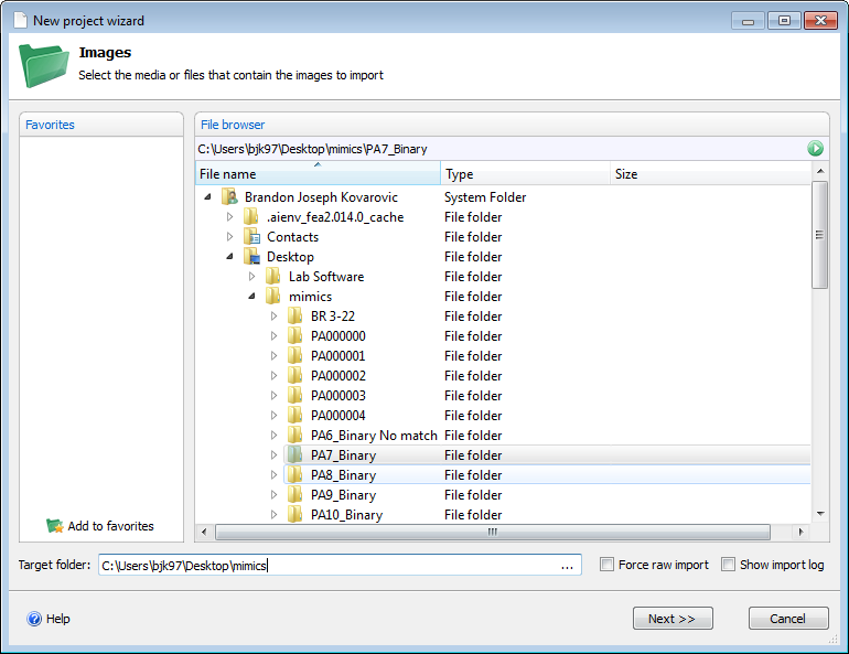
Select the folder containing the DICOM images of the CT scan, MIMICs will detect the order based on the file names of images. Also select the output folder for the project.

Press next and confirm all the settings and order of the images.

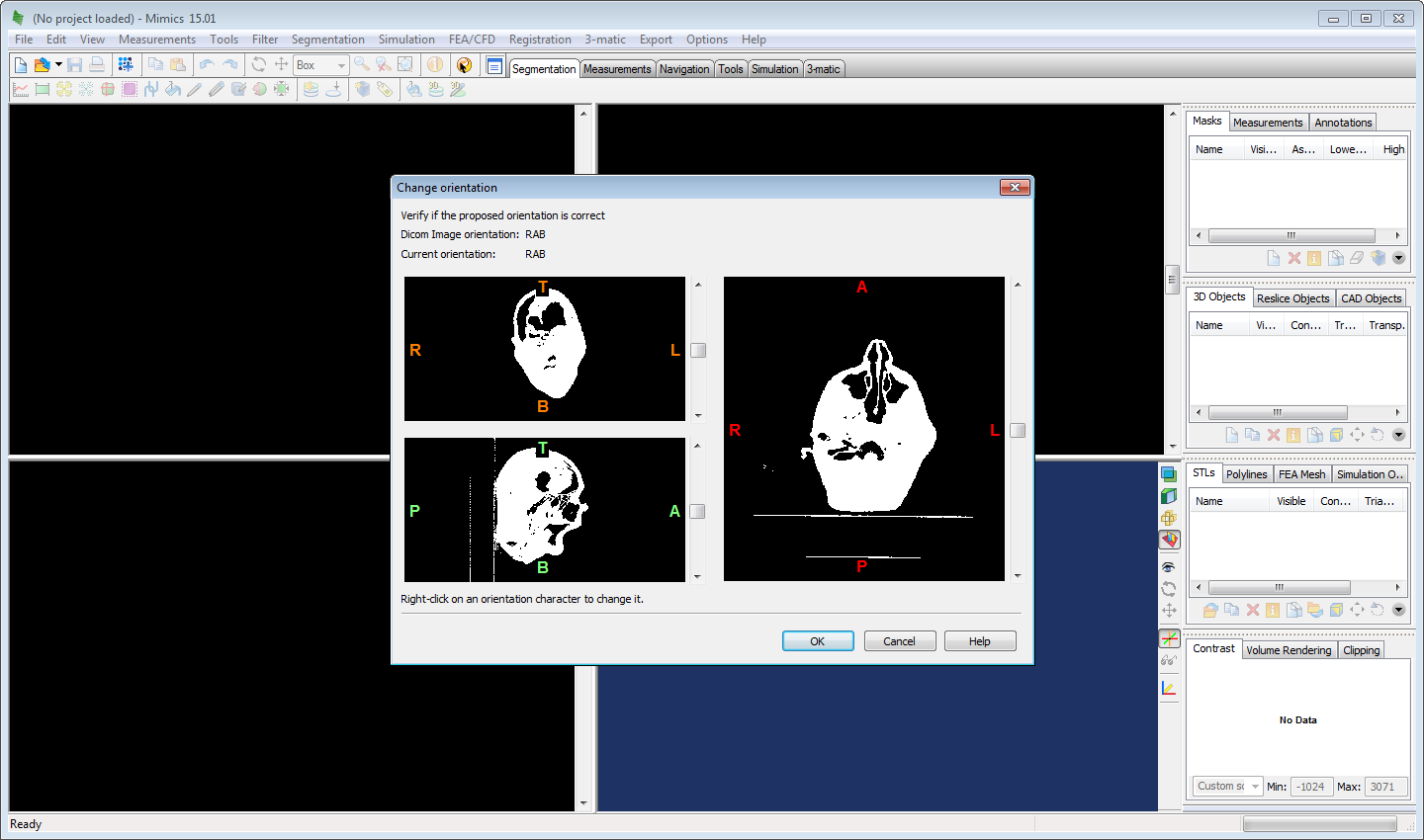
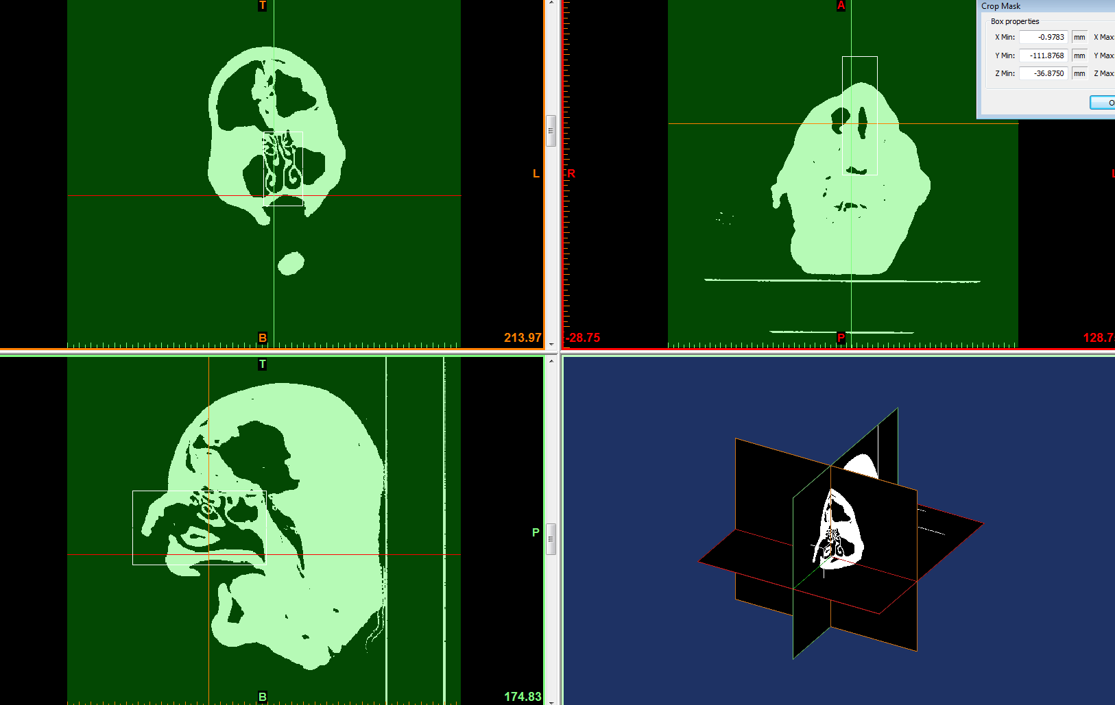
Set all the planes of the images, aligning the posterior, top and right side to the images.

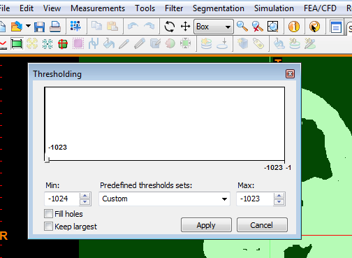
The next step is to start creating the masks of the images that contain the outline of the volumes used in the CFD calculation. Creating the mask is based on first selecting a threshold of pixel values or tissue densities that the primary mask will have. Since the images are now binary, the images have only two pixel values. Press the threshold button to create the first mask. The primary mask should contain both pixel values to include both the air and the tissue, so make sure the min and max values are at the lowest and highest values or that the slider has the entire range.

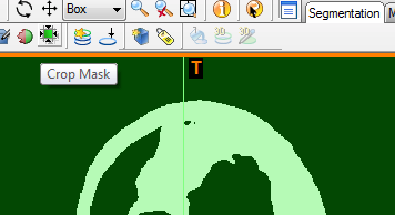
Next the mask needs to be cropped with the crop mask button to select only the area around the nasal cavity. Adjust the height, width and length of the rectangular mask in the three viewing planes.


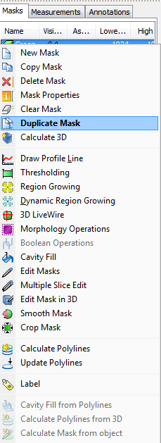
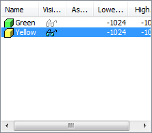
Now on the right side there is the created and cropped mask, by default labeled "Green", right click on this mask and select Duplicate Mask. This will create a copy of the mask in a new color. The purpose of having multiple masks is that you can do boolean operations to the masks, subtracting one or adding one to the other. In this tutorial we will later subtract the secondary mask from the primary to leave a third mask containing only the nasal volume.

Now deselect the visibility or the 'eye glasses' on the primary mask to have only the secondary yellow mask visible and only edit that mask.

Right click on the black background of the Coronal plane and select Zoom to Full Screen. The Coronal plane will allow us to distinguish the nasal geometry the easiest.

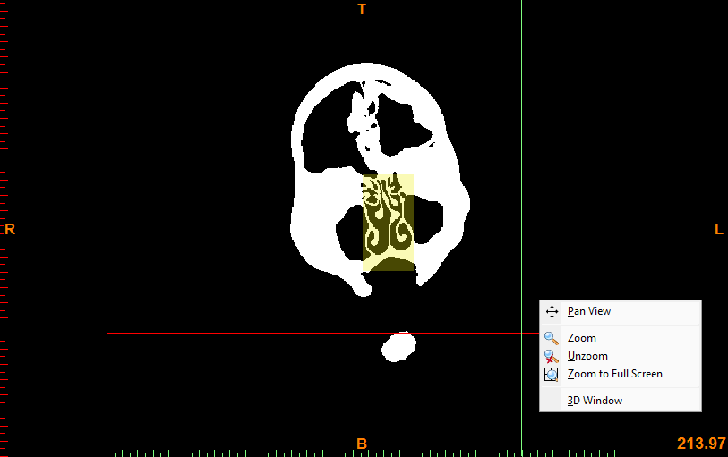
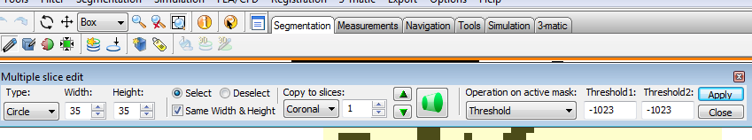
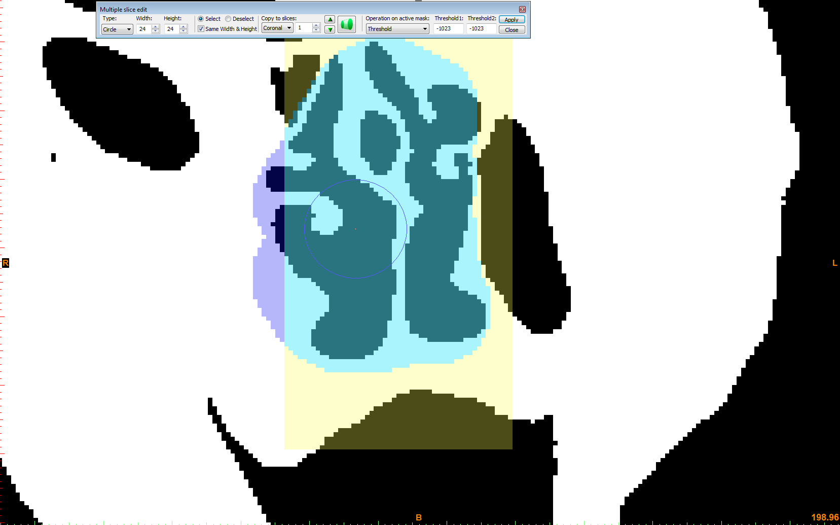
Next select the Multiple Slice Edit button. In the appeared function box, select Coronal under the planes, and Thresholding as the operation. Lower the thresholding values to only include the values of the tissue. The next step is very long and tedious. Middle mouse scroll all the way back to the nasopharynx, and begin highlighting the area of the cavity. Then scroll, image by image selecting the cavity in each slice. There is an Interpolate button that will linearly connect the regions in between distant slices, but this is difficult to do with the complex nasal geometry. Continue all the way to the nostrils and remove any sinus geometry and select apply.


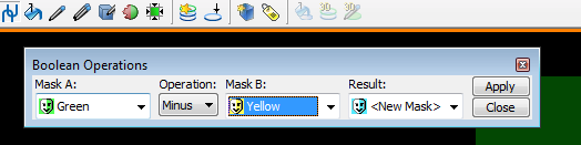
Next with the Boolean Operation button, remove the secondary mask yellow from the primary green mask.

Right clicking on the new mask and selecting Edit Mask in 3-D will allow you to flatten the inlet and outlet geometries by removing additional pixels in at the nostrils and nasopharynx. This also gives you a chance to smooth any geometry and trim any sinus cavities you may have missed.

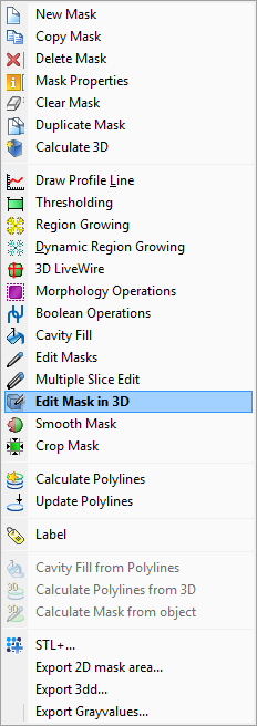
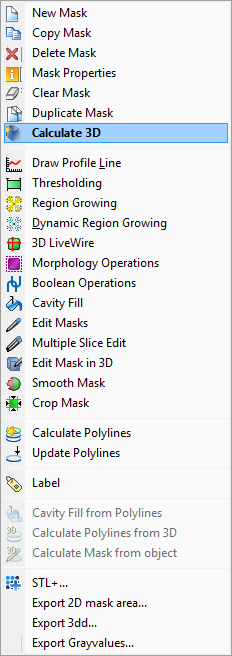
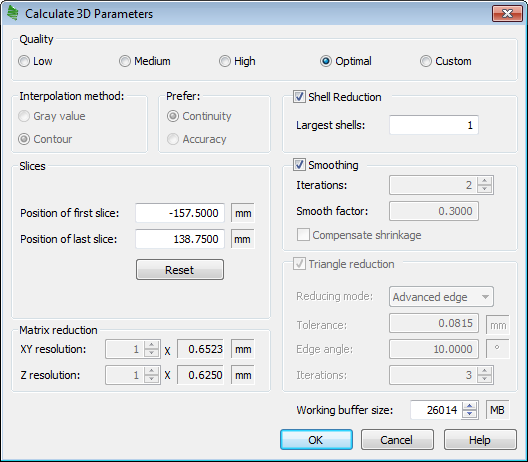
Next right click on the third mask and select Calculate 3-D, this will make the primary STL geometry. In the options, leave the optimal quality, but select the shell reduction, set at 1. This will create only a single largest volume and make sure there are no floating pixels or random disconnected geometries. Also select the smoothing option, this will help smooth out the pixels give a nice smooth geometry for FLUENT. After the 3-D is created, additional Smoothing can be done and Triangle Reduction so that the exported STL is as small and correct as possible.


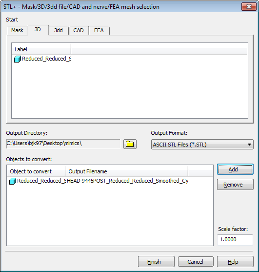
Right click on the 3D and select STL+ option.

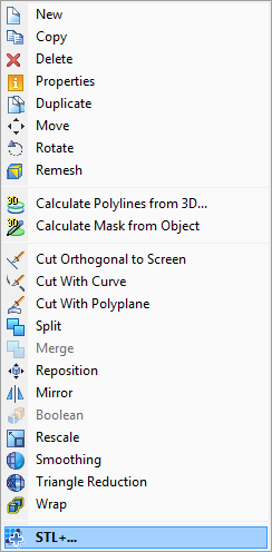
Select the created, smoothed and reduced 3D. Select Add and finally finish. In the directory selected in the very beginning will be the final STL geometry. Save the MIMICs project and close out the program.