 Sign-up for free online course on ANSYS simulations!
...
The following should appear in the FLUENT window:

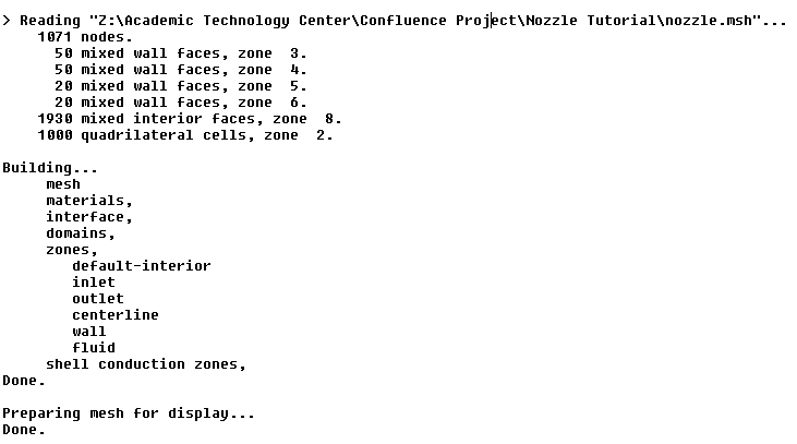
Check that the displayed information is consistent with our expectations of the nozzle gridmesh.
Check and Display
...
Mesh
First, we check the grid to make sure that there are no errors.
Main Menu > Grid Under Problem Setup > General > Mesh > Check (button)
Any errors in the grid would be reported at this time. Check the output and make sure that there are no errors reported.
Grid Main Menu > Mesh > Info > Size
How many cells and nodes does the grid have?
The mesh is being displayed by default but the steps to accomplish this when the grid is not being displayed are the following:
Main Menu > Display > GridMesh
Make sure all items under Surfaces is selected. Then click Display. The graphics window opens and the grid mesh is displayed in it.
Some of the operations available in the graphics window are:
Translation: The grid mesh can be translated in any direction by holding down the Left Mouse Button and then moving the mouse in the desired direction.
...
Zoom Out: Hold down the Middle Mouse Button and drag a box anywhere from the Lower Right Hand Corner to the Upper Left Hand Corner.
The grid mesh has 50 divisions in the axial direction and 20 divisions in the radial direction. The total number of cells is 50x20=1000. Since we are assuming inviscid flow, we won't be resolving the viscous boundary layer adjacent to the wall. (The effect of the boundary layer is small in our case and can be neglected.) Thus, we don't need to cluster nodes towards the wall. So the grid mesh has uniform spacing in the radial direction. We also use uniform spacing in the axial direction.
Look at specific parts of the grid mesh by choosing each boundary (centerline, inlet, etc) listed under Surfaces in the Grid Mesh Display menu. Click to select and click again to deselect a specific boundary. Click Display after you have selected your boundaries.
...
Set the total pressure (noted as Gauge Total Pressure in FLUENT) at the inlet to 101,325 Pa as specified in the problem statement. For a subsonic inlet, Supersonic/Initial Gauge Pressure is the initial guess value for the static pressure. This initial guess value can be calculated from the 1D analysis since we know the area ratio at the inlet. This value is 99,348 Pa. Note that this value will be updated by the code. After you have entered the values check that under the Therma Thermal tab, the Total Temperature is 300K. Then click OK to close the window.
...