 Sign-up for free online course on ANSYS simulations!
...
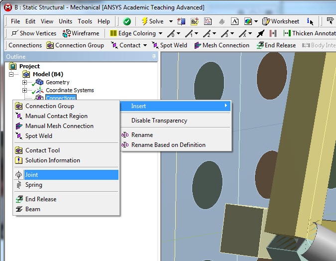
First, we need to create a Joint Connection: Right click on Connections and select Insert>Joint.
Now, use the Vertex tool to select the point where the line bodies intersect, "above" the flexure mount and apply it as the "Mobile" Geometry selection. Then select the face of the flexure mount near the vertex (using the surface select tool) and then apply it as the Reference Geometry selection.
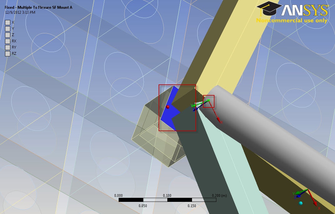
Do this for the remaining flexure mounts, and the center submount. There should be a total of 9 Joints created from this.
...
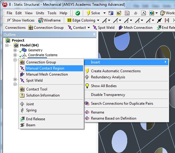
Insert a new Manual Contact Region. Right Click on Connections, Insert>Manual Contact Region.
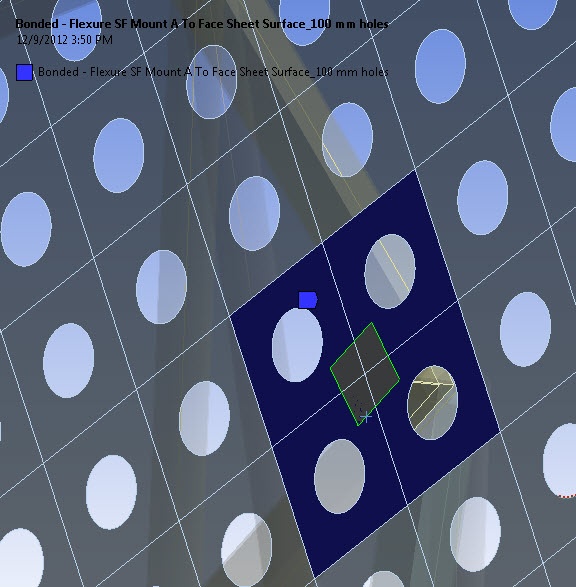
For this contact, you will want to select the four faces of the shell geometry (Face Sheet Surface_100mm holes) and apply it as the Target body (Red). Then select the flexure mount surface near it and apply it as the contact bodies (blue). You should be able to select it through the shell model.

Repeat for the remaining seven flexure mount and center subframe connections.
...
This step is very similar to step 2, except that you should select the Edges of the Flexure mount as the Contact bodies (4 edges), and the same shell surfaces as the target bodies (4 bodies).
Repeat for the remaining mounts.
...
Now is the time to use the alterations to the mount pad we made in the Geometry step. Create a new Joint connection, and select the the created surface on the mount pad as the Reference geometry. Select the vertex of the line bodies as the Mobile geometry selection.

Repeat for the remaining mounts: 6 vertices.
...
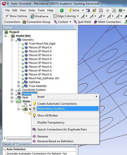
Run the Redundancy tool to make sure you haven't over-defined a connection.
Physics Setup
...
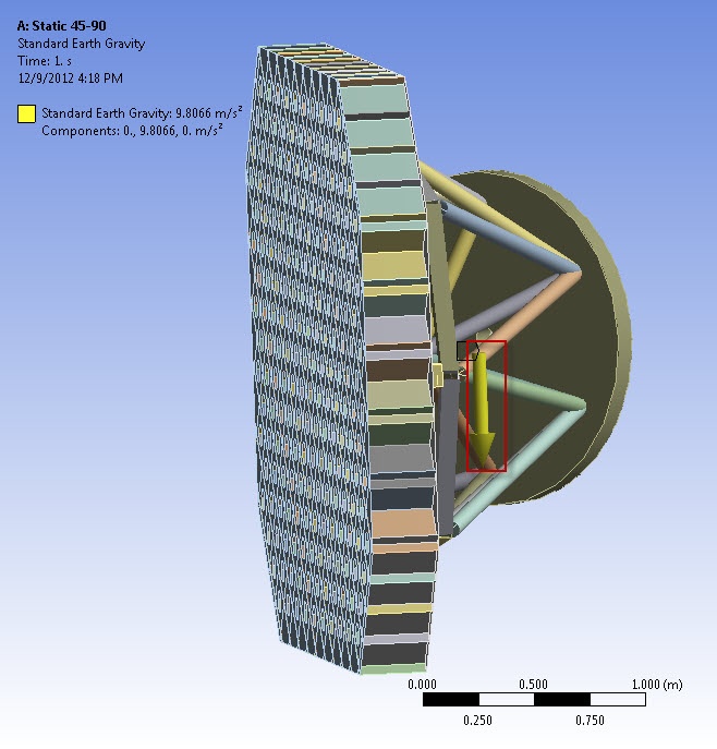
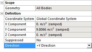
Right click on Static Structural. Insert>Standard Earth Gravity change the direction to +Y Direction.
Next, we need to apply the force from the mirrors attached to the truss. This is a force of 1500N in the direction of gravity. We need to apply this across this to the outside subsurface, which has 280 faces. Instead of selecting them all manually, simply select one, and then use the "Extend to limits" function. This will quickly select all the faces in that plane.
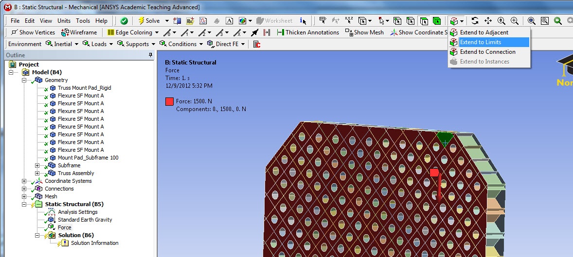
Using the Components definition, create 1500N in the positive Y direction.
Lastly, we need to create the support on the Truss. Create a fixed support at attach it to the bottom of the mount pad.
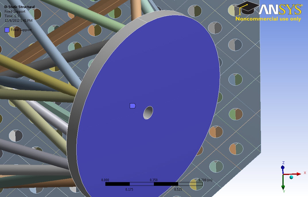
While this fixes one direction of motion, it does not prevent the base pad from translational movement parallel to its plane. To constrain this, we create a Cylindrical Fixed Support and apply it to the middle hole.
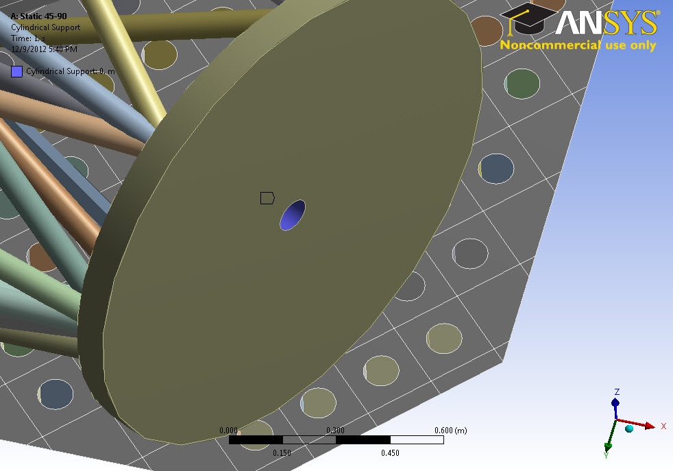
We don't want to over-constrain it, so make sure only the Tangential definition is fixed, letting the Radial and Axial movements be free.

This completes the Setup of the Truss's physical attributes.
...