 Sign-up for free online course on ANSYS simulations!
 Problem Specification |
Step 6: Specify boundary conditions |
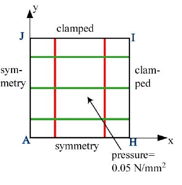
The boundary conditions given in the problem specification are summarized in the schematic below. Keep in mind that the edge conditions need to be applied to the plate as well as the stiffeners.
Apply Symmetry along AH
We'll apply this BC in two steps:
...
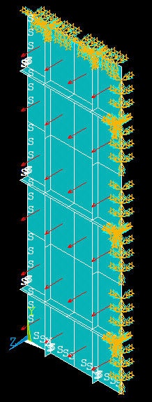
Select the entire model: Click Select All and then Replot in the Select Entities menu. You should see the S symbol along the edges where the symmetry BC has been applied.
Apply Symmetry along AJ
We'll first select all edges along AJ. Go back to Select Entities menu: Leave Lines and By Location in place. Choose X coordinates. Under Min,Max, retain 0. This will select all lines whose centers lie at x=0. Make sure From Full is selected. Click Apply.
...
Select the entire model: Click Select All and then Replot in the Select Entities menu.
Apply Clamped BC along HI
Now that we've gotten the hang of this boundary business, let's mop up Operation BC's in short order.
...
Select Entities menu: Select All and Replot
Apply Clamped BC along JI
Select Entities menu: Leave Lines, and By Location in place. Choose Y coordinates. Under Min,Max, enter L1. This will select all lines whose centers lie at y=L1. Make sure From Full is selected. Click Apply.
...
Select Entities menu: Select All and Replot
Save: Toolbar > SAVE_DB
Apply Pressure on Plate
Utility Menu > PlotCtrls > Numbering: Turn off line numbering.
...
Select Entities menu: Select All, Replot and Cancel. You should now see the entire model. Review that all the BC's have been applied correctly.
Save: Toolbar > SAVE_DB
Create Log File
In parametric studies to be undertaken later, we'll start with the log file containing the commands from the first six steps that we just went through. To save this log file, select
...