 Sign-up for free online course on ANSYS simulations!
...
Set Mesh Size Along Edges
We'll use the previously-defined parameters NDIV_X, NDIV_Y and SIZE_Z to set the mesh size along edges. The table below describes what each parameter is and the value we have assigned to it.
...
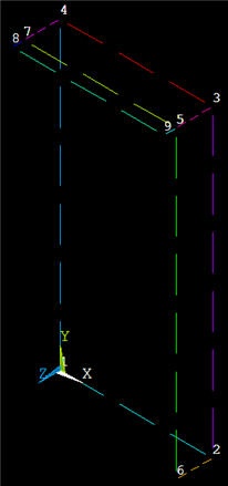
Edges along z are of two different lengths, as should be apparent from the geometry display. For instance, the edge between keypoints #5 and #9 is smaller than that between keypoints #3 and #5. By setting the element size rather than the number of divisions, we can use the same parameter for both edge lengths.
Bring up the MeshTool: Main Menu > Preprocessor > MeshTool
We are going to continually use the MeshTool to generate the mesh. So resize and rearrange the windows slightly so that you can access the MeshTool, ANSYS GUI, and tutorial simultaneously.
If you have trouble selecting the correct line below, hold down the left mouse button until the line is selected and then release the left button. If you want to deselect a line, right-click to go into deselect mode, left-click on the line to be deselected and right-click again to go back into select mode.
Under Size Controls and Lines, click Set. Pick all four lines in the x-_direction. and click OK in the pick menu. Enter NDIV_X for _ No. of element divisions and click Apply.
Next, pick all three lines in the y-direction and click OK in the pick menu. Enter NDIV_Y for No. of element divisions and click Apply.
Last, pick all five lines in the z-direction and click OK in the pick menu. Enter SIZE_Z for Element edge length. Make sure No. of element divisions is blank. Click OK.
Plot lines to see the element divisions along edges and check that they have been set correctly: Utility Menu > Plot > Lines. If you made an error, repeat the above steps before saving.
...
Recall that the plate and the horizontal and vertical stiffeners have different thicknesses which have been assigned to different "real constant" sets. Jog your memory about which thicknesses have been assigned to which "real constant" sets in Step 2.
We'll first mesh the plate using real constant set #1. Under Element Attributes in MeshTool, click on Set. You will see that the element type and material number are already set and the default real constant set is #1. These are the options we need for the plate; so these don't need to be changed. Click Cancel.
Plot areas: Utility Menu > Plot > Areas
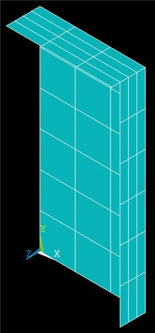
Click on Mesh in MeshTool. Pick area A1 and click OK. The resulting mesh for the plate is displayed.
Generate Mesh for Vertical Stiffener
Under Element Attributes in MeshTool, click on Set. Set Real constant set number to 2 and click OK.
Plot areas: Utility Menu > Plot > Areas
Click on Mesh in MeshTool. Pick area A2 and click OK. The resulting mesh for the plate is displayed.
Generate Mesh for Horizontal Stiffener
Under Element Attributes, click on Set. Set Real constant set number to 3 and click OK.
Plot areas: Utility Menu > Plot > Areas
Click on Mesh in MeshTool. Pick areas A3 and A4 and click OK.
Let's change the graphical display so that the geometry is displayed as a solid model with the shell thicknesses shown. At the command prompt, type /eshape, 1 and then select Utility Menu > Plot > Replot. When the /ESHAPEcommand in issued, ANSYS uses the real constants associated with each element to determine its shape. (Note that commands are not case-senstive.)
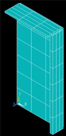
Do the relative thicknesses of different parts of the shell look correct? Feel free to manipulate the graphical display to check this.
You can access different model views such as front, right, isometric etc. using the buttons to the right of the graphics window. At the bottom of this row of icons is the Dynamic Model Mode . Clicking this icon allows you to manipulate the model using the mouse (alternatively, you can hold down the Ctrl key). To see the help page on this mode, right-click on the icon and select Dialog Overview > Pan, Zoom, Rotate > Dynamic Mode: Model.
Save: Toolbar > SAVE_DB
...