 Sign-up for free online course on ANSYS simulations!
Step 5: Mesh geometry
Bring up the MeshTool:
Main Menu > Preprocessor > Meshing > MeshTool
...
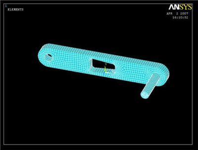
Now repeat the procedure with the crank shaft. Remember that the shaft element size must be the same as the crank so that the shaft elements and crank elements in the hole line up. (You can ignore any errors that may pop up regarding element size. ANSYS is complaining because the shape of some of the quadrilateral elements in high stress areas have a non-ideal element shape) Your final meshed model should look like the following. We're almost ready to solve the problem.
Save Your Work
Toolbar > SAVE_DB