 Sign-up for free online course on ANSYS simulations!
Step 5: Mesh geometry
Each truss member can be represented as a 2D Spar element. We'll use the MeshTool to mesh the geometry with this element.
...
The MeshTool is used to control and generate the mesh.
Set Meshing Parameters
We'll now specify the element type, real constant set and material property set to be used in the meshing. Since we have only one of each, we can assign them to the entire geometry using the Global option under Element Attributes.
...
Click OK. ANSYS now knows what element type (and associated constants) and material type to use for the mesh.
Set Mesh Size
Since a LINK1 element is equivalent to a truss member, we will specify that we want only one element per line. This is a subtle point and also very unusual; in most problems, you want to subdivide your part into many elements.
...
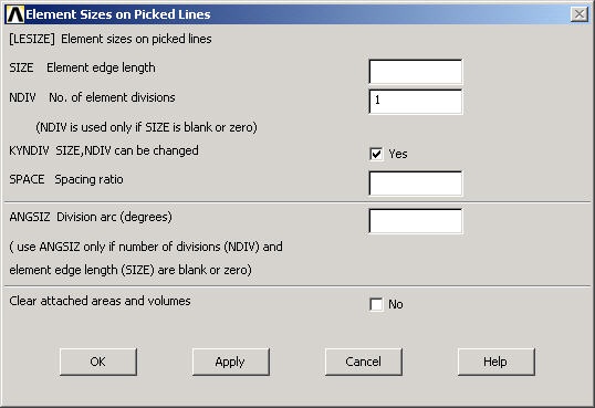
In the pick menu that comes up, click Pick All (since we want the specification of mesh size to apply to all lines in the geometry). This brings up the Element Sizes on Picked Lines menu. Specify No. of element divisions to be 1. Click OK*.* ANSYS will now use 1 element to mesh each line.
Mesh Lines
In the MeshTool, make sure Lines is selected in the drop-down list next to Mesh. This means the geometry components to be meshed are lines (as opposed to areas or volumes, as we'll see later). Click on the Mesh button.
...
NUMBER OF LINES MESHED = 3
MAXIMUM NODE NUMBER = 3
MAXIMUM ELEMENT NUMBER = 3
Close the MeshTool.
View Element List
Utility Menu > List > Elements > Nodes + Attributes
...
Close the window listing the elements.
View Node Location
In order to see where the nodes are located, you can look at the list of nodes.
...
Close the window listing the nodes.
Save your work
Toolbar > SAVE_DB