 Sign-up for free online course on ANSYS simulations!
...
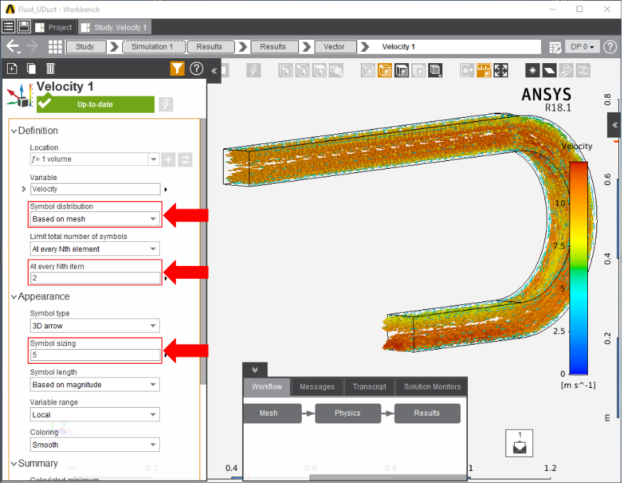
Select the velocity vector to edit the setting in which the vectors are defined. Make sure to update the Symbol distribution to Based on mesh and set At every Nth item to 2. Press the play button in the model window to see how these velocity vectors develop over time.
To find the total pressure on the walls of the duct, select Contour from the Results add dropdown menu. Select all of the outside faces of the flow volume and change the Variable to TotalPressure. This effectively will plot the pressure on the duct by calculating the pressure at the boundary layer.

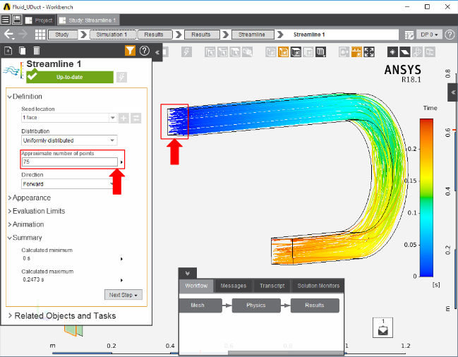
Streamlines can also be computed by picking the Streamline option in the Add drop down menu near the Results category. Select the inlet as the Seed location. Retain Distribution as Uniformly distributed and input 50 to 100 for Approximate number of points. If desired change the Wire thickness in the Appearance section to alter how big the streamlines are. Press the play button in the model window to see how these streamlines develop over time.
To create a plot of the pressure inside the fluid volume, create a plane and orient it to bisect the flow volume. Once the plane has been created, use the Add drop down menu to create a contour whose location is the plane and the variable is TotalPressure.

Go to Step 6: Verification & Validation
...