 Sign-up for free online course on ANSYS simulations!
...
Left click (and hold) on Fluid Flow (FLUENT) , and drag the icon into the empty space in the Project Schematic. Your ANSYS window should now look comparable to the image below.
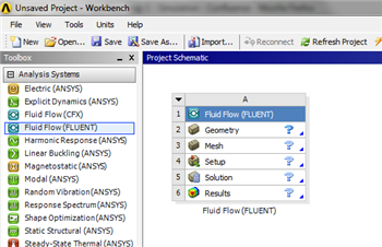
Since we selected Fluid Flow (FLUENT), each cell of the system corresponds to a step in the process of performing CFD analysis using FLUENT. Rename the project to Laminar Pipe.
We will work through each step from top down to obtain the solution to our problem.
...
This will create a new surface SurfaceSK1. Under Details View, select Sketch1 as as the Base Objects by selecting one of the lines of the sketch and by clicking apply. Then select the thickness to be 0.1m and click Generate to generate the surface.
...
At this point, you can close the Design Modeler and go back to to Workbench Project Page .
Save the project by clicking on the "Save As.." button,  , which is located on the top of the Workbench Project Page . Save the project as "LaminarPipeFlow" in your working directory. When you save in ANSYS a file and a folder will be created. For instance if you save as "LaminarPipeFlow", a "LaminarPipeFlow" file and a folder called "LaminarPipeFlow_files" will appear. In order to reopen the ANSYS files in the future you will need both the ".wbpj" file and the folder. If you do not have BOTH, you will not be able to access your project.
...