 Sign-up for free online course on ANSYS simulations!
...
We set the geometry upstream to be shorter because we have less activity before flow through cylinder. We set the geometry downstream of the cylinder to be relatively longer because we want to make sure such that the downstream farfield boundary is conditions will not affected by the wake generatedaffect the flow near cylinder.
Create a Working Directory
...
Operation Toolpad > Geometry Command Button ![]() > Edge Command Button
> Edge Command Button ![]() > Create Edge
> Create Edge ![]() > Arc
> Arc ![]() >
> 
| Warning | ||
|---|---|---|
| ||
(Click here for animated steps)
...
| Info | ||
|---|---|---|
| ||
Create Front Outer Boundary
...
Operation Toolpad > Geometry Command Button ![]() > Edge Command Button
> Edge Command Button ![]() > Move/Copy Edges
> Move/Copy Edges 
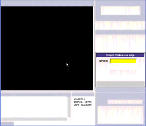
Select Select the front cylinder edge. Make sure that the Copy is checked. Under Operation, select Scale. Next to Factor, enter a value of 10. This means that the radius of influence we create will be 10 times the size of the cylinder.
...
Select the vertex and associated edge. Make sure to select Split edge. At the end of this, you should have 4 new vertices.
Connect all Vertices
Finally, connect all the remaining vertices KL, LM, NO, OP, FI and GJ.
...