Hello! This is a documentation of my process of using and interfacing with Caravel on the eFabless test board (specifically, the ECE 5745 tapeout received in June 2023). The idea is that other uses should be able to reproduce my results based on this documentation.
Prerequisites
In order to successfully complete this tutorial, you must have:
Hardware
- A Caravel test board with the ECE 5745 tapeout attached
- A SPI Driver
- Two Micro-USB cables (to connect your computer to the SPI Driver and test board)
- (Optional) An ESD-safe mat. While strictly-speaking optional, it is a good idea to have to avoid any ESD buildup from damaging our chip
Software
Note: Technically, Verilator is also a prerequisite, but we need a specific version, so we will install this later
Additionally, it is highly recommended that you perform this on a Mac or Linux machine; if you are using a Windows machine, you will probably need to work inside of WSL or something similar (I recommend just installing Ubuntu on WSL)
Setup
Since we have to complete this tutorial locally (as we'll be plugging things into our computer), there's a fair bit of setup to do!
First, let's clone the main testing repository (located here, if you're curious)
git clone git@github.com:cornell-c2s2/ece5745_testing.git
cd ece5745_testing
TOPDIR=$PWD
From here, the first thing that we need to do is install Verilator. However, PyMTL3 needs a specific version, which often isn't the default one. To help with this, we've created a custom command:
make verilator
We're specifically looking for version 4.036. If you already have it installed, hooray! If you don't, this command will install it via Homebrew and a custom Ruby script. If you already have a different version of Verilator installed, it will prompt you to uninstall that version and re-run the command (on Homebrew, that would be brew remove verilator).
In addition, we also need to install PyMTL3 itself, along with a few other Python dependencies. To avoid messing up your normal Python environment, we will be doing this inside of a virtual environment. First, build the virtual environment by running the command:
make venv
Once your virtual environment is built, you can enter it by sourcing our script to set up the environment
source pymtl_env.sh
Notice how your prompt has changed to indicate your PyMTL3 environment! You'll need to be in this environment anytime you're using this tutorial. If you ever want to exit it and return to your normal Python environment, you can simply use the command deactivate (or an alias for it, noenv)
RTL Testing
First, we should verify that our tests pass with our given RTL. This helps make sure that our environment is set up properly, as well as that there aren't any issues with the tests (assuming that our RTL is correct and tested before ![]() ). Let's start by looking at
). Let's start by looking at project-group99, a simple GCD Unit.
First, let's make our build directory inside of the sub-repository:
cd $TOPDIR/project-group99
mkdir -p sim/build
cd sim/build
From here, we can run all of the tests associated with the design using pytest:
pytest ../tapeout
You should get that all of the tests pass - congrats! This means that our environment is set up properly with PyMTL. If you get any errors, you can use the -v flag (for verbose) and --tb=short flag with the above command to get insight into which tests are failing and why (respectively).
Connecting Hardware
Alright - now that we've made sure our tests and testing environment are good, it's time to break out the hardware.
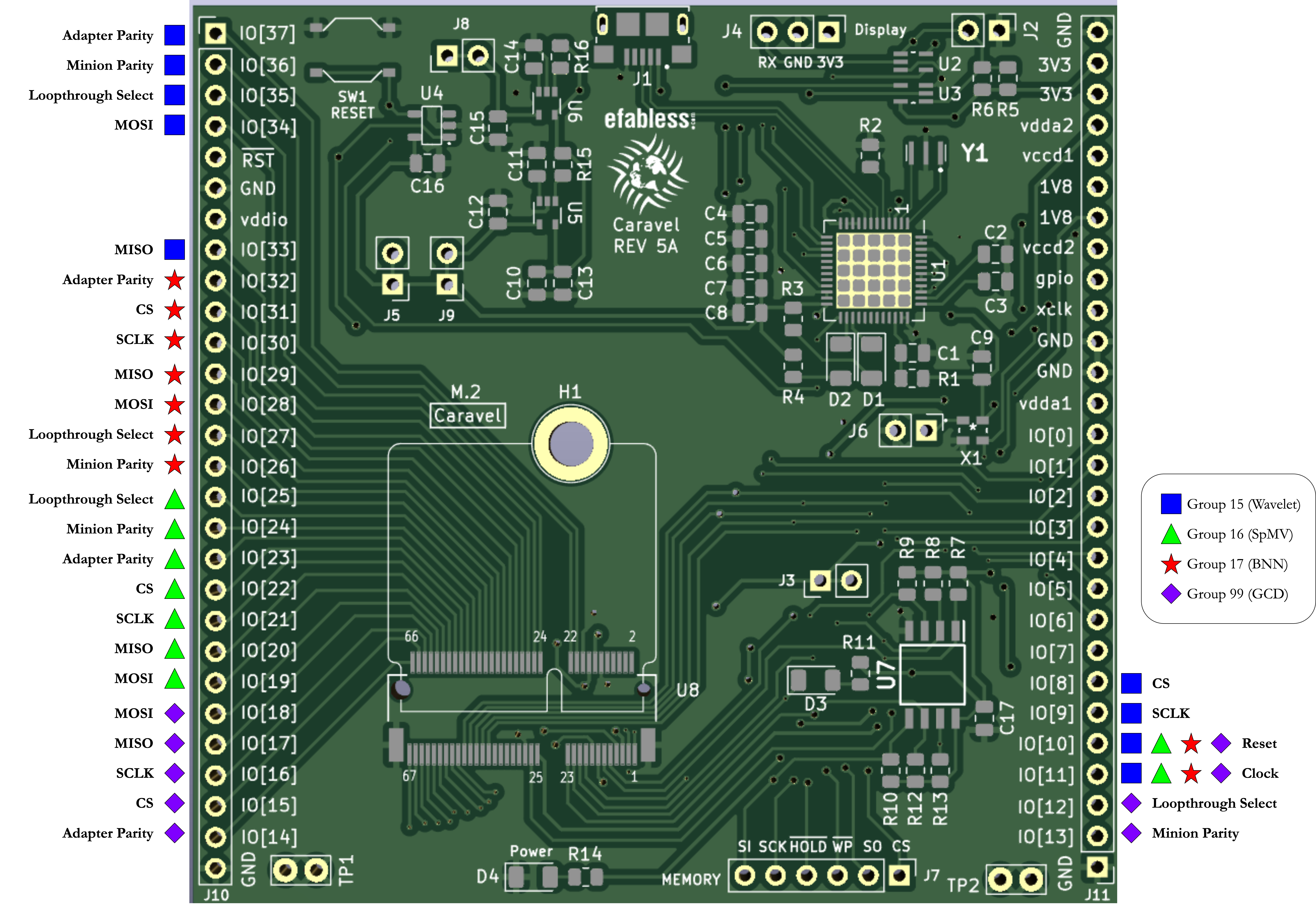
Carefully take out the Caravel chip, as well as the SPI Driver. If you had an ESD protection mat, they would go on this for the duration of the tutorial. Connect the SPI Driver's SPI signal lines to the chip in the correct places. Reference the ECE 5745 chip pinout (especially the board diagram), remembering that we are using Group 99. Connect the SCLK, CS, MOSI, and MISO lines for Group 99, as well as the group's reset signal to the A port of the driver, and the group's loopthrough select signal to the B port of the driver. Finally, connect the group's clk signal to the xclk port on the Caravel board.
After that, all that's left to do is to plug in the boards to your computer:
- Plug your two Micro USB cables into the SPI Driver and the Caravel test board
- First, plug in the SPI Driver to your computer, then plug in the Caravel board. When the board is plugged in, a red LED should indicate that it is receiving power
The order that they are plugged in does matter - it affects which ports they're assigned to on your computer. Our code in the SPI Test Harness is expecting the SPI Driver at the first port, so it should be the first USB device plugged into your computer. If you have issues with this later on, see the FAQ below regarding port issues (you will have to change the port regardless if you are on Windows)
Note additionally that if you are using Apple Silicon, you will have to change the port as well, as they no longer mount to the same place, see the FAQ below regarding port issues, as well as using ls /dev to give insight as to where the device is mounted.
Flashing Firmware to the Caravel Chip
The first thing that we need to do is confirm that we can flash our code to the chip, and interact with the RISCV SoC. To do this, we'll use a simple "blink" test, which blinks an on-board LED.
Luckily, we can accomplish this using the Makefile commands from our blink directory inside our firmware_vex directory (which was adapted from eFabless' code, located here). With the hardware connected properly, run the following commands:
cd $TOPDIR/firmware_vex/blink
make clean flash
clean will remove any previous build artifacts, and flash will compile the code using the RISC-V toolchain, as well as use a custom Python script to flash the code to the Caravel chip. After the command finishes, you should see an LED blinking on the board; this is attached to the primary GPIO on the SoC, which is continuously blinking the LED in a loop. This verifies that we can interact with the processor on-board and run basic code.
Testing our Custom Hardware - GCD
Great - now that we know how to test our RTL, and load software onto the chip, it's time we combine the two to test the hardware on the chip itself!
The first thing we need to do is configure our GPIO's correctly for our hardware's intended functionality. Caravel allows the GPIOs to be dynamically set up in various different ways (input versus output, core versus custom hardware, etc.), so we need to load software to do this based on the inputs and outputs of our custom hardware. We've created an ece5745.c file that configures all of the GPIO's, applies the configuration, and blinks the on-board LED when finished. To do this, we can flash the C code, similarly to before:
cd $TOPDIR/firmware_vex/ece5745
make clean flash
Once this is done, you should see the LED blinking continuously, indicating that the software was flashed successfully
Finally, we can re-use our test cases, interfacing with the SPI Driver instead of the RTL design. To do this, we've modified the SPI_v3/components/SPITestHarness.py test harness to interface with either one, depending on whether a flag, --physical, is set in our pytest command. With this, we can easily re-run our tests on the actual chip. Assuming everything is wired correctly, you should be able to accomplish this with a similar command to our RTL testing:
cd $TOPDIR/project-group99/sim/build
pytest ../tapeout --physical
You should not only see the tests passing on your terminal, but the SPI Driver sending and receiving signals from the chip. Once this finished, you should see all of the tests pass - great job!
Further Exploration
To go beyond this basic demonstration, there are some other avenues that you can explore to further test the chip and understand the setup:
- Explore the
project-group99folder. This design is the GCD Unit from ECE 5745's Verilog tutorial. Notice how it is wrapped with the SPI Minion, and how it is interfaced to in the tests using the SPI Test Harness. Understanding this will allow you to create you own designs using the SPI components - Explore the other designs present (Projects 15, 16, and 17). You can test them similarly, making sure to adjust your connections to the chip to account for the new projects
- Disconnect one of the wires when testing. What happens to the tests? What happens on the SPI Driver screen? Does this support what you expect to occur? (Note that some tests in the projects don't use the SPI Test Harness, and are hard-coded to test only RTL, so they may pass regardless)
- Run the tests for one design while physically wired to a different design. What happens to the tests? Does this support what you expect to occur? (Note that one test is for the SPI Harness in loopback mode, where the data in is the same as the data out regardless of the design - what happens specifically with this test?)
FAQ
Q: Where is the clock coming from?
A: The test board contains an on-board MEMS oscillator, which produces a 10MHz clock that is used by default. If you wish to supply an external clock, disable the MEMS oscillator (X1) by shorting J6 (pulling the EN line low), and driving the xclk pin as you please
Q: I'm getting an error "extension `zicsr' required"
A: This has to do with the compiler directives. eFabless' flow specifically targets -march=rv32i; this is the baseline RISCV ISA, which doesn't support control and status register (CSR) operations. In order to tell the compiler to support these instructions, we need to modify our GCC commands (usually in Makefiles) to -march=rv32i_zicsr. I've changed this in our directory, as well as opened a pull request to change it for eFabless, but in case you come about it, this is the solution. (Note: The reason this wasn't needed before has to do with the different versions of the RISCV toolchain; older GCC versions wouldn't need this, but recent versions do)
Q: I'm getting "Module not found" or "Error: No backend available"
A: This has to do with Python being able to find all of your installations (with the latter being regarding Python's ability to find libusb , a dynamically linked library to support pyusb, a Python module for interfacing with USB ports). These shouldn't be an issue if you're using a virtual environment as described above. However, if you choose to use your main environment, make sure that your Python3 and pip3 installations correspond to each other (i.e. are in the same directory) - you can check using which python/which pip. If they are in the same directory, check here as well
Q: When I try to run the tests, I get that GCC doesn't recognize a lot of flags?
A: *sigh* This is likely because MacOS (for some reason) said "Eh, clang is close enough to GCC", and used it instead when you run the gcc command. While they are close, they are not identical, and don't support the same flags.
Try running gcc --version. If the output says "Apple Clang" or something like that, this bug is for you ![]()
First, we'll need to install the correct version of GCC. Since we already have Homebrew installed, we can just do it with that:
brew install gcc
Once that's done, we have the correct version of GCC installed...however, in some cases, it's not linked correctly. Try gcc --version again; if it now references Homebrew, you're done! If not, keep going...
By default, Homebrew installs executables in $HOMEBREW_PREFIX/bin; in most cases, $HOMEBREW_PREFIX is to /usr/local, but on newer Macs, it is set to /opt/homebrew (see here). While this doesn't cause issues in most cases, it means that commands in /usr/bin are preferred over those installed by Homebrew in /opt/homebrew. However, commands in /usr/local/bin would be preferred over those in /usr/bin, due to their ordering in our PATH (see the Linux Tutorial: Chapter 4: Environment Variables, Aliases and our PATH). While we could change our PATH to fix this, it might change other dependencies.
Instead, we'll create symlinks in /usr/local/bin to them! (See Chapter 7: Links). Run the following commands, replacing the xx in the commands with the version of gcc you have from gcc --version. For instance, my GCC is version 13, so I would run these commands with gcc-13:
sudo ln -s $HOMEBREW_PREFIX/bin/gcc-xx /usr/local/bin/gcc
sudo ln -s $HOMEBREW_PREFIX/bin/g++-xx /usr/local/bin/g++
This should create a symbolic link to the correct version of gcc (as well as g++, in case we need it later) in /usr/local/bin. Verify with gcc --version that your default GCC is the Homebrew version - you should be good to go!
Q: When using the SPIDriver, I get an error "Could not open port"
A: Make sure that your SPIDriver is connected properly first ![]() . From there, it may be an issue of port naming; see the SPI Driver Guide (specifically, page 18). You may need to change the port name for the SPI Test Harness that you're trying (ex. for
. From there, it may be an issue of port naming; see the SPI Driver Guide (specifically, page 18). You may need to change the port name for the SPI Test Harness that you're trying (ex. for project-group99, the port name used is in project-group99/sim/SPI_v3/components/SPITestHarness.py, and is set to /dev/ttyUSB0 by default).
Q: My physical tests are stalling for no apparent reason
A: Part of the SPITestHarness that looks for the SPI Driver is likely responsible. Since accessing the driver doesn't work 100% the first time, it iterates in a loop until it finds the driver. However, if the driver isn't plugged in correctly, or if the port is incorrect, this loop will keep trying to access the driver forever.
You can test out whether you can access the driver outside of the test. From within your virtual environment, type python to access a Python shell, then run:
from spidriver import SPIDriver
port = '/dev/ttyUSB0'
driver = SPIDriver( port )
The error from the last line should further indicate any issues that you're having. A likely culprit is that it couldn't open the port - see above