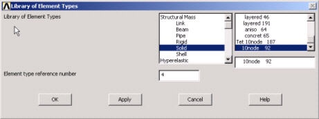
We will use SOLID92 elements to mesh the upper and lower disks. This is a 3D 10-Node Tetrahedral Structural Solid element.
Main Menu > Preprocessor> Element Type > Add/Edit/Delete > Add...
This brings up the Library of Element Types menu. Select Structural Solid in the left field and Tet 10node 92 in the right field. Click OK.

In contact problems, one needs to identify the surfaces that are expected to come into contact, and group them into either "contact" surfaces or "target" surfaces. There are various guidelines for defining contact and target surfaces. One of them is size. If one surface is larger than the other surface, the larger surface should be the target surface. |
For our problem, there are two surfaces that are expected to come into contact. These are the curved areas that are initially in contact at the point of contact. We will define the curved surface of the lower disk to be the target surface (larger of the two). As a result, the curved surface of the upper disk will be the contact surface.
Once the contact and target surfaces are identified, the next step is to select the contact and target elements. The contact elements will overlay the solid elements (SOLID92) and will describe the boundary of the upper disk (contact surface) that is expected to come into contact with the lower disk (target surface). Think of the contact elements as the skin of the surface that is expected to come into contact. Let's take a look at the different elements available.
Close the Element Types menu.
Utility Menu > Help > Help Topics
Select the Index tab and type in contact analysis as the keyword. Double-click on Contact analysis which should be the first topic listed. This brings up the Chapter 10 Contact help page. Click on ANSYS Contact Capabilities which is the third topic from the top. Note that ANSYS supports three types of contact models: node-to-node, node-to-surface, and surface-to surface. Each type of model uses a different set of contact elements. Table 10.1 summarizes the different elements available.
For our problem, the initial interaction between the disks is at a point. However, we expect the surfaces of the disks to come into contact once the force is applied. If you read the ANSYS Contact Capabilities help page, you will find that CONTA175is one of the node-to-surface contact elements that can be used to represent contact between a node and a surface or between two surfaces. This element also supports 3-D structural contact analysis, as shown in the Contact Capabilities table (10.1), and we'll use it to mesh the contact surface.
For the target surface, we can use either TARGE169 or TARGE170 elements. Since TARGE169 elements support 2-D analysis and TARGE170 support 3-D analysis, we will use TARGE170 elements to mesh the target surface.
Main Menu > Preprocessor> Element Type > Add/Edit/Delete > Add...
This brings up the Library of Element Types menu, select Contact in the left field and 3-D target 170 in the right field. Click Apply.
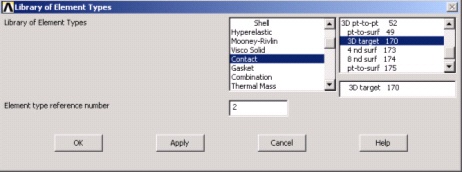
Select Contact in the left field and pt-to-surf 175 in the right field. Click OK.
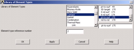
Close the Element Types menu.
Main Menu > Preprocessor> Real Constants > Add/Edit/Delete > Add
This brings up the Element Type for Real Constants menu with a list of the element types defined in the previous step.
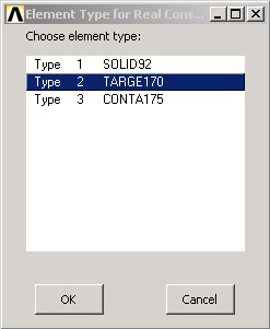
Select SOLID92 and click OK. You should get a note "The SOLID92 element type does not require real constants". Take a look at the help pages for SOLID92, under SOLID92 Input Summary, and you will find that there are no real constants to be specified for this element. Close the warning message.
Now, let's look at the real constants for TARGE170. Click on Add. Select TARGE170 and click OK.
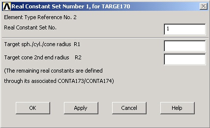
Real constants R1 and R2 define the geometry of the target elements. For contact problems, it is recommended to first try using the default settings, and then change them if difficulties are encountered or the analysis has special situations. ANSYS will default R1 and R2 to zero once the target elements are generated. We'll use the default values for our analysis. Click Cancel.
Now, let's look at the real constants for CONTA175. Click on Add, select CONTA175 and click OK.
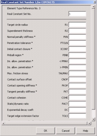
As you can see, ANSYS uses several real constants to control contact behavior. As in the previous case, we'll use the default values set by ANSYS for our analysis. Refer to the help page for CONTA175, for a detailed description of the real constants for this element.
Note that for some of the real constants, such as FKN and FTOLN, you can specify either a positive or a negative value. ANSYS interprets a positive value as a scaling factor and a negative value as the absolute value.
Click Cancel and then Close the Real Constants menu.
Toolbar > SAVE_DB
Go to Step 3: Specify material properties
Go to all ANSYS Learning Modules