Divide the geometry into suitable components. This will be an "assembly" in a standard CAD package.
Save the CAD geometry in STEP format (.stp) and then import the .stp file into ANSYS. This is the recommended format.
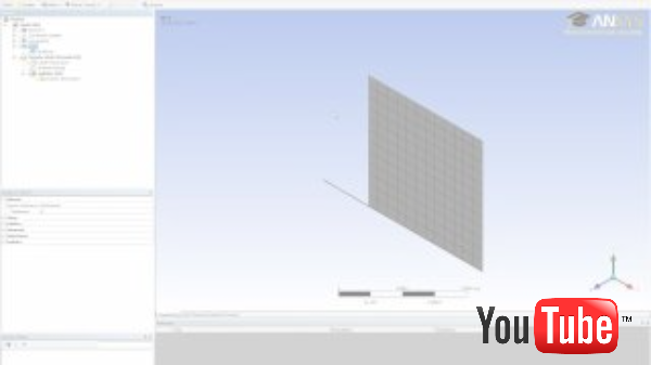
Double-click on Geometry in the project page in ANSYS, select all the parts in the tree using Ctrl-click. Then right-click and select "Form new part".
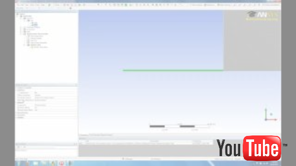
After opening the model in ANSYS Mechanical, you will see a "Connections" folder in the tree. Make sure that the "contact" (i.e. interface) regions are all set to "bonded." This is the default for interfaces between flush entities.