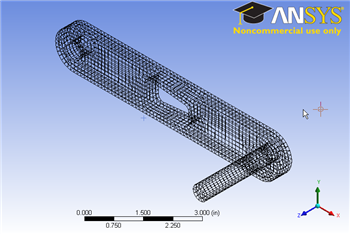
This is the mesh that appear in the Graphics window on the right.

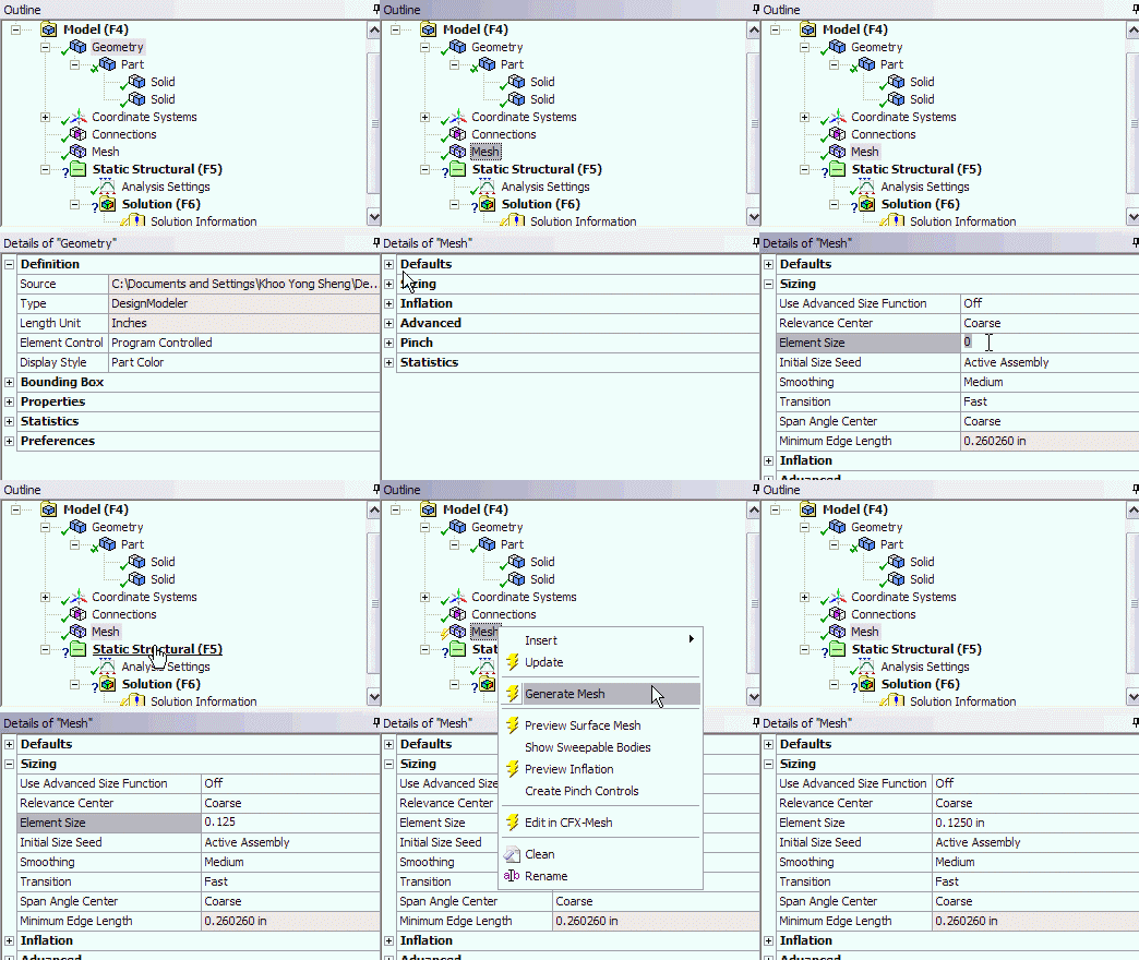
In the Crank cell, right click on Model, and click Edit...
A new window Mechanical Modeler will open. We will start with the default mesh generation method. Under Outline, right click on Mesh and click Generate Mesh. This will give us mesh that ANSYS mesher thinks appropriate for our geometry. We see that ANSYS is smart enough to create a mesh that sweep across the cross sectional area of the crank. This is the type of mesh we are seeking for our geometry. However, sizing wise, the mesh is too coarse. We will have to increase the number of elements.
Under Outline, click on Mesh. Next under Details of "Mesh", expand the Sizing tab and we will specify the element size that we desire. Element size of 0.125 in seems to be a good start. Next to Element Size, enter 0.125. Finally, click on Generate Mesh again.

This is the mesh that appear in the Graphics window on the right.

https://confluence.cornell.edu/download/attachments/111236474/Crank%20Mesh.png |
You should have 18205 nodes and 3582 elements for your mesh. Click on Statistics under Details of "Mesh" to see that.
For future reference, the default mesh might not produce the desirable mesh that we want. To specify our own mesh control, right click on Mesh and select Insert. This way, we can insert meshing type and control that we desire. To learn more about different meshing methods, please refer to the Mechanical Help at the top menu.
See and rate the complete Learning Module
Go to all ANSYS Learning Modules