 Sign-up for free online course on ANSYS simulations!
| HTML |
|---|
<div style="background-color: yellow; border: 2px solid red; margin: 4px; padding: 2px; font-weight: bold; text-align: center;">
This page has been moved to <a href="https://courses.ansys.com/index.php/courses/vertical-axis-wind-turbine-part-1/">https://courses.ansys.com/index.php/courses/vertical-axis-wind-turbine-part-1/</a>
<br>
Click in the link above if you are not automatically redirected in 10 seconds.
</div>
<meta http-equiv="refresh" content="10; URL='https://courses.ansys.com/index.php/courses/vertical-axis-wind-turbine-part-1/'" /> |
| Include Page | ||||
|---|---|---|---|---|
|
| Include Page | ||||
|---|---|---|---|---|
|
...
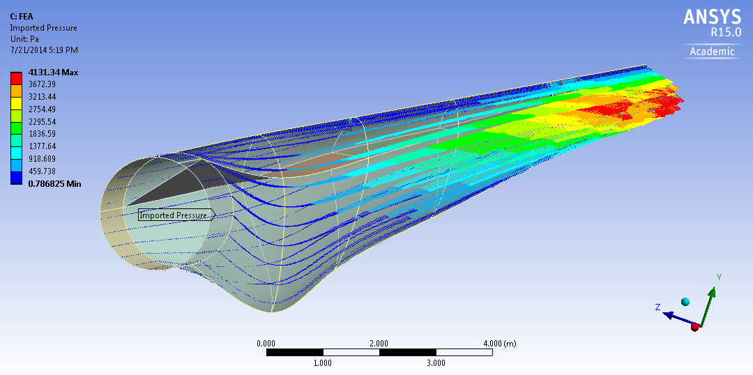
This tutorial considers the deformation due to aerodynamic loading of a wind turbine blade by performing a steady-state 1-way FSI (Fluid-Structure Interaction) analysis. Part 1 of the tutorial uses ANSYS Fluent to develop the aerodynamics loading on the blade. In part 2, the pressures on the wetted areas of the blade are passed as pressure loads to ANSYS Mechanical to determine stresses and deformations on the blade.
The blade is 43.2 meters long and starts with a cylindrical shape at the root and then transitions to the airfoils S818, S825 and S826 for the root, body and tip, respectively. This blade also has pitch to vary as a function of radius, giving it a twist and the pitch angle at the blade tip is 4 degrees. This blade was created to be similar in size to a GE 1.5XLE turbine. For more information on the dimension characteristics of this blade, please see this M.Eng report (note that model in the present tutorial has an additional 2 meter cylindrical extension at the root to make it more realistic).
...
The turbulent wind flows towards the negative z-direction (into the page on the above diagram) at 12 m/s which is a typical rated wind speed for a turbine this size. This incoming flow is assumed to make the blade rotate at an angular velocity of -2.22 rad/s about the z-axis (the blade is thus spinning clockwise when looking at it from the front, like most real wind turbines). The tip speed ratio (the ratio of the blade tip velocity to the incoming wind velocity) is therefore equal to 8 which is a reasonable value for a large wind turbine. Note that to represent the blade being connected to a hub, the blade root is offset from the axis of rotation by 1 meter. The hub is not included in our model.
...
Part 1
In this section of the tutorial, the blade geometry is imported, a mesh is created around the blade and the Fluent solver is then used to find the aerodynamics loading on the blade, the fluid streamlines and the torque generated. We will use air at standard conditions (15 degree celcius). Its density is 1.225 kg/m^3 and its viscosity is 1.7894e-05 kg/(m*s).
...