 Sign-up for free online course on ANSYS simulations!
| Include Page |
|---|
...
|
...
|
| Include Page |
|---|
...
|
...
|
...
Geometry
For axisymmetric models, we use cylindrical polar coordinates (r, θ, z) with no variation in the θ direction. So we can just model a slice in the (r, z) plane as shown below.
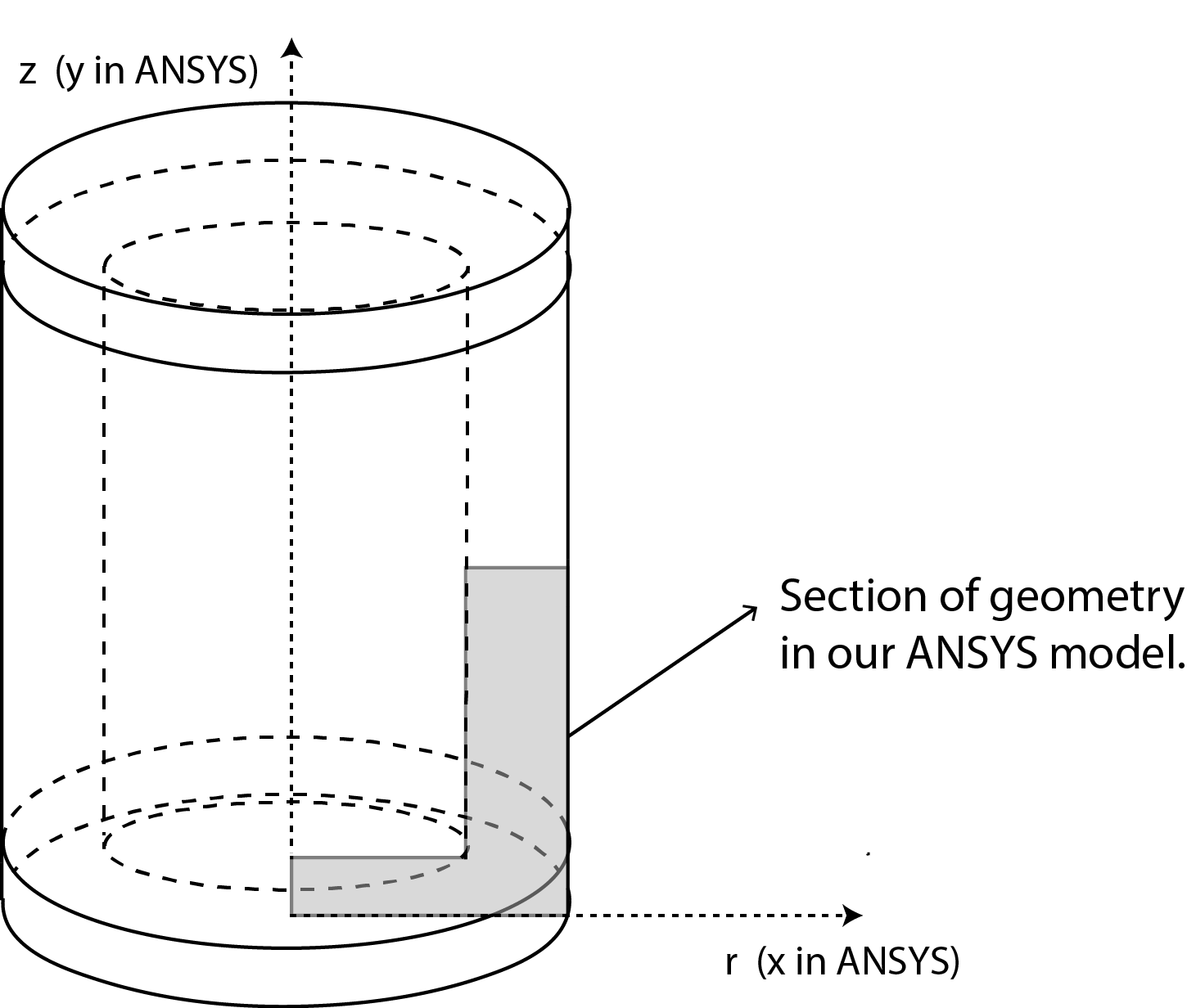
In ANSYS, the radial direction is x (rather than r) and the axial direction is y (rather than z). Confusing! We recommend that in an axisymmetric analysis, you think of the directions in ANSYS as radial & axial rather than "x" and "y".
Note that for axisymmetric models in ANSYS, the y-axis is always the axis of symmetry. The corresponding 3D geometry can be generated by revolving the 2D section 360° about the y-axis (we'll do this later in the Numerical Results step).
...
| Note |
|---|
For users of ANSYS 15.0, please check this link for procedures for turning on the Auto Constraint feature before creating sketches in DesignModeler. |
We will first create a sketch and then a "surface body" from the sketch. The "surface body" is nothing but an area that we can mesh and apply boundary conditions toextrude it to make our beam. We will then split our beam in 3 sections in order to create lines to apply our loads on. The video below shows the steps to be followed to create the sketch and surface body, the beam and to slice the body in three sections.
...
| HTML |
|---|
<iframe width |
...
="600" height="338" src="//www.youtube.com/embed/ |
...
CbQmHcCLmw8?rel=0" frameborder="0" allowfullscreen></iframe> |
...
Continue to Step 3 - Mesh