 Sign-up for free online course on ANSYS simulations!
| Include Page | ||||
|---|---|---|---|---|
|
This page covers
...
follow-on
...
exercises
...
to
...
the
...
...
...
...
.
...
In
...
particular,
...
it
...
shows
...
how
...
to
...
add
...
a
...
strain
...
gage
...
to
...
the
...
ANSYS
...
model
...
to
...
predict
...
the
...
strain
...
that
...
would
...
be
...
measured
...
by
...
a
...
gage
...
mounted
...
on
...
the
...
crank
...
model.
...
Strain
...
Gage
...
Modeling
...
The
...
following
...
video
...
shows
...
how
...
to
...
add
...
a
...
surface
...
to
...
the
...
crank
...
model
...
to
...
find
...
the
...
average
...
strain
...
over
...
the
...
area
...
covered
...
by
...
a
...
strain
...
gauge
...
mounted
...
on
...
the
...
crank.
...
The
...
video
...
includes
...
audio
...
as
...
do
...
other
...
videos
...
on
...
this
...
page.
...
Note
...
that
...
you
...
have
...
to
...
make
...
the
...
following
...
modifications
...
to
...
the
...
procedure
...
shown
...
in
...
the
...
video:
...
- Using
...
- "Automatic
...
- Connections"
...
- to
...
- connect
...
- the
...
- crank
...
- arm
...
- and
...
- the
...
- gage
...
- doesn't
...
- always
...
- work.
...
- An
...
- alternate
...
- procedure
...
- to
...
- manually
...
- connect
...
- the
...
- two
...
- entities
...
- is
...
- shown
...
- in
...
- a
...
- later
...
- video
...
- below.
...
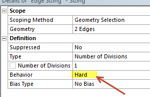
- When
...
- specifying
...
- the
...
- edge
...
- sizing
...
- for
...
- the
...
- gage,
...
- set
...
- Behavior=Hard
...
- as
...
- in
...
- the
...
- snapshot
...
- below.
...
- Otherwise,
...
- ANSYS
...
- might
...
- over-ride
...
- your
...
- edge
...
- setting
...
- and
...
- you
...
- will
...
- get
...
- more
...
- than
...
- one
...
- element.
HTML <iframe width="600" height="338" src="//www.youtube.com/embed/94o6t-LCzl4?rel=0" frameborder="0" allowfullscreen></iframe>
...
An overview of the procedure followed in the video and explanation of the associated steps can be found in this powerpoint presentation from MAE 3272, Spring 2013.
Our ANSYS Mechanical 14.0 model with a strain gage mounted can be downloaded here for your review. Download the .wbpz file and double-click on it to load it in ANSYS Workbench. To save the file in the usual .wbpj format, select File > Save as. To reduce the file size, the results have not been saved. You'll have to clear all results by selecting (right-click)Results
...
- >
...
- Clear
...
- Generated
...
- Data
...
- in
...
- the
...
- project
...
- page.
...
- Then,
...
- re-solve
...
- in
...
- ANSYS
...
- Mechanical
...
- (the
...
- red
...
- M
...
- in
...
- the
...
- taskbar)
...
- to
...
- see
...
Manually Connecting Crank Arm and Gage
The above video shows how to add a connection between the crank arm and the gage using Create Automatic Connections. But this automated procedure doesn't always work. In that case, one has to connect the two entities manually using Insert > Manual Contact Region as shown in the video below.
| HTML |
|---|
results. \\ \\ [!clear_results.png|width=350!|^clear_results.png]\\ \\ h3. Manually Connecting Crank Arm and Gage The above video shows how to add a connection between the crank arm and the gage using {color:#660099}{*}{_}Create Automatic Connections{_}{*}{color}. But this automated procedure doesn't always work. In that case, one has to connect the two entities manually using {color:#660099}{*}{_}Insert > Manual Contact Region{_}{*}{color} as shown in the video below. \\ {html}<iframe width="600" height="338" src="//www.youtube.com/embed/KhyN1puzSY0?rel=0" frameborder="0" allowfullscreen></iframe>{html} \\ h3. Meshing with Hexahedrals using the |
Meshing with Hexahedrals using the Multi-Zone
...
Method
...
The
...
multi-zone
...
method
...
in
...
ANSYS
...
- Gives
...
- hexahedral
...
- or
...
- box
...
- elements
...
- for
...
- certain
...
- geometries
...
- Chops
...
- up
...
- the
...
- domain
...
- into
...
- regions
...
- which
...
- can
...
- be
...
- "hex-meshed".
...
- These
...
- regions
...
- often
...
- have
...
- a
...
- shape
...
- that
...
- can
...
- be
...
- created
...
- though
...
- extrusion
...
- The
...
- default
...
- meshing
...
- method
...
- often
...
- gives
...
- a
...
- tetrahedral
...
- mesh
...
- which
...
- has
...
- lower
...
- accuracy
...
- than
...
- a
...
- hex
...
- mesh
...
- for
...
- the
...
- same
...
- number
...
- of
...
- nodes.
...
- The
...
- advantage
...
- of
...
- tetrahedrals
...
- is
...
- that
...
- you
...
- can
...
- mesh
...
- any
...
- general
...
- geometry
...
- while
...
- pure
...
- hex
...
- meshes
...
- can
...
- be
...
- created
...
- only
...
- for
...
- some
...
- geometries.
...
The
...
steps
...
for
...
using
...
the
...
multi-zone
...
meshing
...
method
...
for
...
the
...
bike
...
crank
...
geometry
...
are
...
shown
...
in
...
the
...
video
...
below.
| HTML |
|---|
\\ {html}<iframe width="600" height="338" src="//www.youtube.com/embed/vmVwnsO53yo?rel=0" frameborder="0" allowfullscreen></iframe>{html} \\ h3. Creating a New Coordinate System in ANSYS Mechanical If your default coordinate system is not centered on one of the holes in the crank, or you wish to learn how to define new coordinate systems inside the mechanical window, please refer to the following video: \\ {html} |
Creating a New Coordinate System in ANSYS Mechanical
If your default coordinate system is not centered on one of the holes in the crank, or you wish to learn how to define new coordinate systems inside the mechanical window, please refer to the following video:
| HTML |
|---|
<iframe width="600" height="338" src="//www.youtube.com/embed/gWJlPBX3C_Y?rel=0" frameborder="0" allowfullscreen></iframe>{html}
\\
\\
h1. Comments
h2.
Please click on the following link to access the Piazza discussion page for this tutorial.
\\ {menulink:custom|link=https://piazza.com/class/hj629p862t37jm?cid=23|target=_blank}Piazza Discussion - Bike Crank (Part 2){menulink}
\\
First time using our Piazza discussion board? Please follow this {menulink:wikipage|page=Piazza Sign-Up Tutorial|target=_blank}Sign-Up Tutorial{menulink} to enroll in our class\! Don't worry, it's quick and easy\! After enrollment, you will be able to access the discussion pages for all SimCafe tutorials\! Rest assured that you can post anonymously if you wish.
\\
\\
[Go to all ANSYS Learning Modules|ANSYS Learning Modules] |
Comments
| Include Page | ||||
|---|---|---|---|---|
|
| Include Page | ||||
|---|---|---|---|---|
|