 Sign-up for free online course on ANSYS simulations!
| Include Page | ||||
|---|---|---|---|---|
|
| Include Page | ||||
|---|---|---|---|---|
|
Geometry
| Note |
|---|
For users of ANSYS 15.0, please check this link for procedures for turning on the Auto Constraint feature before creating sketches in DesignModeler. |
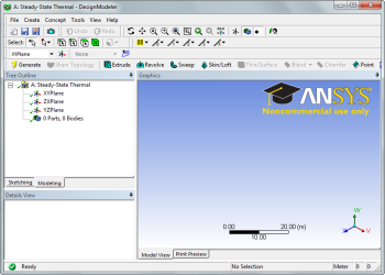
Change the Geometry Properties
In the Steady-State Thermal box, right click Geometry and select Properties . We need to allow ANSYS to recognize line bodies as valid geometries. We accomplish this by checking the box marked Line Bodies .
Open the Design Modeler
We are now ready to create the geometry in ANSYS. We will be creating a one dimensional line body to represent the steel bar. To open the design modeler, double click Geometry . After the design modeler is launched, you will be prompted on the default units. Select Meters and press OK .
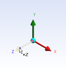
Draw a Line
Next, we need to draw a line to represent the length of the bar. To begin sketching, we need to look at a plane to sketch on. Click on the Z-axis of the compass in the bottom right hand corner of the screen to look at the x-y plane.
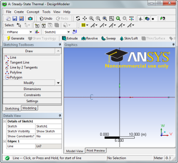
Next, click the Sketching tab in the Outline window to bring up the sketching menu. Next, select  . To draw a line, first click the origin, followed by a point on the x-axis.
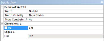
Dimension the line
Next, we need to assign the length to the line. In the Sketching Toolbox click the Dimensions tab, and select  . Click on the line to create a dimension. In the Details window, change H1 to
 5 meters.
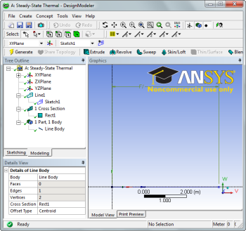
Concept - Line from Sketches
Next, we need to create the line body from the sketch. In the menu bar, click Concept > Lines from Sketches. Next, select the line we drew in the Graphics window, and in the Details window select Apply . Finally, press  to create the line body.
Specify Cross Section
In the menu bar, go to Concept > Cross Section > Rectangular to create a cross section. In the Details menu, specify both B and H to 0.1. After the cross section dimensions are specified, we need to set the cross section to the line body. Expand the 1 Part, 1 Body and select the Line Body . In the Details window, change the Cross Section to Rect1 .
You may now close the design modeler.
Go to Step 3: Mesh