...
Our research found that many of the existing 3D parabolic cookers are not parabolic, but in fact spherical. A spherical reflector is much easier to construct, but is not as effective as a parabolic reflector due to a phenomenon called spherical aberration. The diagram below (Figure 1) demonstrates the effects of spherical aberration in part (a) and its elimination with the parabolic reflector geometry in part (b), when considering light rays of parallel incidence. 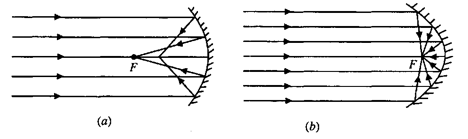
Figure 1: Spherical Reflector and Parabolic Reflector _3_The spherical reflector is unable to focus light at a single focal point; rays that hit the surface further from the optical axis (the horizontal centerline) focus in tighter, and vice versa. The parabolic reflector remedies this problem by focusing all rays to a single focal point (as long as there is parallel incidence). We therefore decided to construct a true parabolic reflector, not a spherical one.
We also needed to determine whether to construct a shallow or deep paraboloid. Most 3D parabolic cookers utilize shallow parabola geometry. Shallow reflectors are more mobile and easily manipulated to the angles needed to receive direct sunlight. This also leaves more flexibility for the design of the cooking surface in relation to the reflector.
...
The construction of a 3D parabolic shape is not trivial. We quickly realized the impracticalities of molding sheet metal to the desired shape, and researched methods to build the paraboloid from petals. Figure 2 details how the flat sheet would look with the appropriate partitions, before assembly. 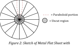 Figure 2: Sketch of Metal Flat Sheet with Partitions
Because Tim provided us with a thin 3' by 4' aluminum sheet, we decided not to cut out a circle and retain as much reflective surface area as possible. We first cut the sheet into 16 sections as shown, and then plotted the paraboloid points needed for a shape with a focal length of 25 cm. A center circle of diameter 3 cm was left uncut to preserve structural stability. Instead of cutting along the paraboloid petals and adhering them edge-to-edge, we folded the slices up and overlapped them to give us room for error. We used reflective tape to keep the petals in place and complete our 3D parabolic reflector. Below is the finished product in Figure 3. Appendix B Table 1 contains the points we used to create these petals, all dimensions in cm. Appendix B Figure 1 details how to plot the points in Table 1. 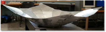
Figure 3: Finished 3D Parabolic Reflector
...
Refer to our finished results shown in Figures 4 and 5.
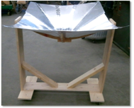
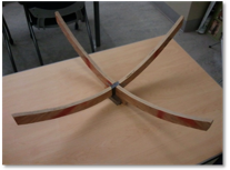
Figure 4 and 5: Reflector and Framework and Reflector Support System
Results
The theoretical focal point (based on our petal design and construction) was calculated to be 9.8 inches. The actual focal point of our reflector was measured to be 10 inches, which is a mere two percent difference from the theoretically calculated point.
When we tested our system, the wooden framework had not been constructed. Therefore, our experimental setup involved a propped wheelbarrow that served as a support for the reflector and allowed us to easily shape and tilt our prototype. Two tripods were used to support a wooden rod that was placed directly across the reflector (Figure 6). Attached to the rod with black duct tape was a small metal corner that could easily absorb heat, and attached to this metal piece was a thermal couple used to record temperatures (Figure 7). This metal piece and thermal couples were placed directly at the paraboloid's focal point.
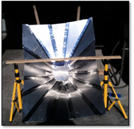
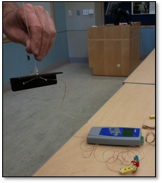
Figure 6 and 7: Reflector Sitting on a Wheelbarrow and Thermal Couple Attached to Metal
The testing showed very promising results (see Figure 8). The peak temperature achieved within minutes was 145 degrees Celsius, with ambient temperature around 11 Celsius. However, testing was not completely conclusive because of the fact that half-way through testing, the tape holding the black metal piece to the wooden rod melted. Hence, the thermal couple fell out of the reflector's focal point and began reading ambient air temperatures instead. The sudden drop in temperature, at around 784 seconds into the trial, is the point where this event occurred.
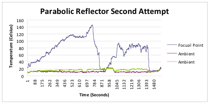
Figure 8: Data from Most Successful Testing
The small spikes and bumps in the recorded data are due to gusts of wind that struck our reflector and constant adjustments that were made to the reflector support system, including tilting of the reflector, movement of the tripods, and adjusting the wooden rod. The adjustments occurred because of the fact that the sun's position is always changing and must be tracked in order to optimize the amount of sunlight focused at the paraboloid's focal point.
No other successful attempts at testing occurred due to time constraints and lack of sufficiently sunny days.
Criteria Review
The following section asserts a critical review of our parabolic solar cooker. We discuss the technical, social, economic, and environmental implications of our prototype.
Technical
Our goal was to create a user-friendly design such that the appropriate components could be removed and/or replaced accordingly. In addition, the oven as a whole should be relatively mobile in order to successfully track the path of the sun. Most importantly, the final prototype should be able to meet the temperature requirements for frying foods (250 Centigrade), and be efficient, durable, and practical enough for everyday use.
Our design is user-friendly in that the reflector, reflector support system, and reflector framework can be easily separated for replacement of any given part. The reflector is mobile (on wheels) and able to tilt to track the sun. Although we did not obtain official test data reaching 250 Centigrade, we have test results yielding temperatures of approximately 140 Centigrade in very little time, which indicates that such temperatures should be possible. Our concentrated cooker as a whole is not finished, lacking a separate cooking surface.
Social
Our social criteria stated that the constructed concentrated cooker should provide concrete results that demonstrate its ability to fry food. These results and their implications were to be communicated to the proper organizations in Nicaragua, as well as to local restaurant owners who previously expressed curiosity towards solar frying. Communication and feedback on the cooker design/implementation would develop greater interest in eventually introducing concentrated cookers to Nicaragua.
We maintained communication with the organizations in Nicaragua over the semester, and informed them that we were working on a parabolic reflector. We received positive feedback, and recommend further informing them about the possibilities of concentrated cookers once concrete temperature testing data reaching 250 Centigrade is achieved.
Economic
We felt that materials in the final design should be available, in terms of both location and cost, to residents in Nicaragua. This would increase the ease with which these ovens could be implemented and built. Ideally, the materials needed should be able to be purchased from local Nicaraguan businesses in order to generate revenue for the local economy.
Our reflector and framework are made of aluminum and wood. Both of these materials are already currently being used in the solar box cookers in Nicaragua.
Environmental
According to Zimmerman's 12 Principles of Green Engineering, materials and energy inputs should be as renewable as possible; the use of a concentrated cooker in favor of a wood-burning stove implements sunlight as an energy source instead of wood. Concurrently, our solar reflector uses sunlight only as a renewable source of heat to bring its focal point area to high temperatures.
Discussion
For much of the design of our reflector and wooden framing, we used materials already found in Winter Lab. Therefore, construction could be carried out almost immediately after design versus waiting two weeks for material shipments to arrive. We designed and built generally at the same time. We found this was easiest since problems cannot always be predicted beforehand. Some ideas that had been originally planned were found to be more difficult to construct than anticipated. Therefore, we tended to design while we were building at some moments (especially for the framework).
Our two attempts at testing revealed that a better support system was needed instead of the makeshift wheelbarrow system. Given the portion of the successful data that we have, we can conclude that our prototype has definite potential to reach temperatures of 250 Celsius. The temperature at the focal point was steadily increasing at the time of failure due to the melted tape. Had failure not occurred, the linear trend shown in Figure 9 estimates that a temperature reading of 250 Celsius may have occurred after approximately 25 minutes, and may even occur faster in non-windy, winter conditions. Specific future tasks include finding a better way to attach the thermal couple to the metal corner, i.e. find a supportive material that will not melt at high temperatures.
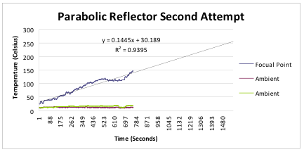
Figure 9: Predicted Trend in Temperature Reading (had failure not occurred)
In addition, this past semester allotted no time to build the cooking surface upon which a pot can be placed. Next semester's work on this project should prioritize this task along with another attempt at successful testing.
Recommendations for Future Teams
There are many suggestions for further improvements that may be research more thoroughly next semester as well. One subject our team was very interested in for future design involved the compound parabola shown in Figure 10. For parabolas, light only focuses on a single point, known as the focal point, when shinned normal to its surface. In order to allow for greater light concentration at the focal point when light is directed at an angle, a compound parabola is needed. The compound parabola basically involves overlapping two parabolas to form one. Properly designed compound parabolas can focus sunlight from many angles. This would mean that the reflector could also focus rays hitting at an angle of 30 degrees, which subsequently means that the compound parabolic cooker could concentrate rays at a focal point for at least 2 hours without adjustment. See Appendix C for further diagrams of the compound parabola.
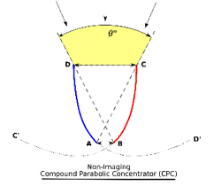
Figure 10: Diagram showing a Compound Parabolic Concentrator 4
Other suggestions for improvement involve making the current concentrated cooker more aesthetically pleasing. This can include painting the wooden framework black to absorb more sunlight.
Conclusion
The prototype constructed this semester shows great potential in its ability to reach high temperatures to fry tortillas. Because of this potential, a wooden framework has already been constructed. This will allow for increased stability in further testing that will occur next semester.
Most women in Nicaragua fry tortillas for their families every morning before the sun rises and before their children walk to school and husbands head to work. Therefore, they would not be able to use our cooker for their needs. However, restaurants need to be able to provide freshly made tortillas throughout the day and would therefore, have great need for our cooker. Hence, we are targeting the production of our cooker toward Nicaraguan restaurants.
Once the cooker has been successfully tested and proven to reach temperatures of 250 centigrade, the prototype can then be introduced to Nicaragua. Constant communication with Groupo Fenix has informed us that they are extremely interested in the concentrated cooker. The group is currently working on the construction of a restaurant to sell solar foods. If our cooker operates well enough to fry tortillas, the group would love to use our prototype. The goal is for introduction to occur in the coming March during spring break.