 Sign-up for free online course on ANSYS simulations!
| Include Page | ||||
|---|---|---|---|---|
|
| Include Page | ||||
|---|---|---|---|---|
|
Solution
...
Although we are only looking for the strain at the strain gauge location, we should also check the deformation of the crank to see if the solution makes intuitive sense. This will allow us to catch any obvious errors we have made setting up the simulation. To add deformation to the solution, first click  to add the solution sub menu to menu bar. Now in the solution sub menu click Deformation > Total to add the total deformation to the solution. It should appear in the outline tree.
...
We will also look at the stress of the bar to verify the simulation against the theory. In the solution sub menu, select Stress > Normal. In the details pane, ensure Orientation is set to X Axis, and Geometry is set to All Bodies. Rename the Stress to StressXX. Now, create another stress the same way, but change Orientation to Y Axis and rename it StressYY
Construction Geometry
The next thing we are going to do is to set up a path where the strain gauge lies on the bike crank. In the outline window, click  . Next, go to Construction Geometry > Path. This will open up the path toolbox in the details window. Creating a path in Workbench is very easy: you just have to specify the starting and ending points of your path and workbench will create it. In the details window, enter (3.3748, -.20512, 0.375) as the starting point and (3.3748, 0.016929, 0.375) as the end point. Change the number of sampling points to 50.
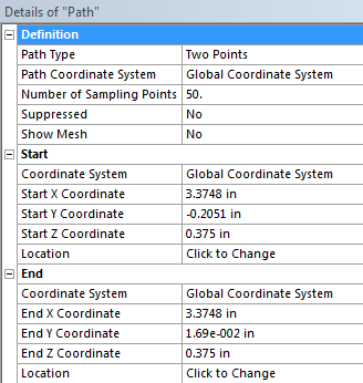
When the parameters of the path have been set, right click on the path you just created in the project tree in the outline window and select Rename. Rename the path, Strain Gauge.
...
In the Solution sub menu select Strain > Normal. Now, we need to specify that we want the strain to be measured at the stain gauge in the y direction. To accomplish this, go to Scoping Method > Path, the select Path > Strain Gauge in the details window. To change the direction of the strain, select Orientation > Y Axis. The rest of the default options should suffice for our simulation.
...