| Panel |
|---|
| Wiki Markup |
|---|
| {alias:contact}
{panel}
Author: Rajesh Bhaskaran, Cornell University
{color:#cc0000}{*}Problem Specification{*}{color}
[1. University Problem Specification
1. Start-up and preliminary set-up |ANSYS - Disks in Point Contact - Step 1]
[
2.
Specify element type and constants|ANSYS - Disks in Point Contact - Step 2]
[3. Specify material properties|ANSYS - Disks in Point Contact - Step 3]
[4. Specify geometry|ANSYS - Disks in Point Contact - Step 4]
[5. Mesh geometry|ANSYS - Disks in Point Contact - Step 5]
[6. Specify boundary conditions|ANSYS - Disks in Point Contact - Step 6]
[7. Solve|ANSYS - Disks in Point Contact - Step 7]
[8. Postprocess the results|ANSYS - Disks in Point Contact - Step 8]
[9. Validate the results|ANSYS - Disks in Point Contact - Step 9]
{panel}
h2. Problem Specification
Consider two semicircular disks made of elastic material which are pressed together by forces P as shown in the figure below. The disks are initially in contact at a single point. The principal radii of curvature of the surface of the upper disk at the point of contact are R{~}1~ and R{~}1~'. Likewise, R{~}2~ and R{~}2~' are the principal radii of curvature of the surface of the lower disk at the point of contact. The line of action of force P lies along the axis that passes through the centers of curvature of the disks and through the point of contact.
!Contact prob spec.jpg!
Figure taken from p. 590 of [Boresi et al|ANSYS - Disks in Point Contact - Step 9].
The intersection of the planes in which the radii R{~}1~ and R{~}2~ (or R{~}1~' and R{~}2~') lie form an angle aas shown in the figure below. Assume that there is no tendency for one disk to slide with respect to the other and, therefore, no friction force is present. Both disks are made of steel (_E{_}{_}{~}1{~}{_}_=E{_}{_}{~}2{~}_=200 GPa and _n{_}{_}{~}1{~}{_}_=_{_}n{_}{_}{~}2{~}_\_=_0.29). The radii of curvature are \_R{_}{_}{~}1{~}_=60mm, _R{_}{_}{~}1{~}{_}_'_=130mm, _R{_}{_}{~}2{~}_=80mm, _R{_}{_}{~}2{~}{_}_'_=200mm. The angle a=0{^}o^ and the applied force _P_=4.5kN. The maximum principal stress and approach (total distance through which the two disks move towards each other as a result of force P) are to be determined using ANSYS. This problem is a modified version of the problem presented in section 17.7, p. 607-608 of [Boresi et al|ANSYS - Disks in Point Contact - Step 9].
!Contact prob spec upper view.jpg!
Figure taken from p. 591 of [Boresi et al|ANSYS - Disks in Point Contact - Step 9].
Go to [Step 1: Start-up and preliminary set-up|ANSYS - Disks in Point Contact - Step 1]
Go to [all ANSYS Learning Modules|ANSYS Learning Modules]constants
3. Specify material properties
4. Specify geometry
5. Mesh geometry
6. Specify boundary conditions
7. Solve
8. Postprocess the results
9. Validate the results |
Problem Specification
Consider two semicircular disks made of elastic material which are pressed together by forces P as shown in the figure below. The disks are initially in contact at a single point. The principal radii of curvature of the surface of the upper disk at the point of contact are R1 and R1'. Likewise, R2 and R2' are the principal radii of curvature of the surface of the lower disk at the point of contact. The line of action of force P lies along the axis that passes through the centers of curvature of the disks and through the point of contact.
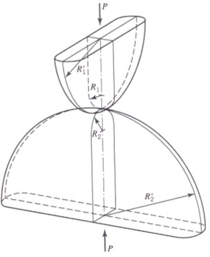 Image Added
Figure taken from p. 590 of Boresi et al.
The intersection of the planes in which the radii R1 and R2 (or R1' and R2') lie form an angle aas shown in the figure below. Assume that there is no tendency for one disk to slide with respect to the other and, therefore, no friction force is present. Both disks are made of steel (E1=E2=200 GPa and n1=n2_=0.29). The radii of curvature are _R1=60mm, R1'=130mm, R2=80mm, R2'=200mm. The angle a=0o and the applied force P=4.5kN. The maximum principal stress and approach (total distance through which the two disks move towards each other as a result of force P) are to be determined using ANSYS. This problem is a modified version of the problem presented in section 17.7, p. 607-608 of Boresi et al.
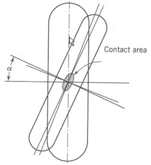 Image Added
Figure taken from p. 591 of Boresi et al.
Go to Step 1: Start-up and preliminary set-up
Go to all ANSYS Learning Modules
 Sign-up for free online course on ANSYS simulations!