 Sign-up for free online course on ANSYS simulations!
Author: Benjamin Mullen, Cornell University
Problem Specification
1. Pre-Analysis & Start-Up
2. Numerical Results
3. Verification and Validation
Exercises
Comments
Exercises
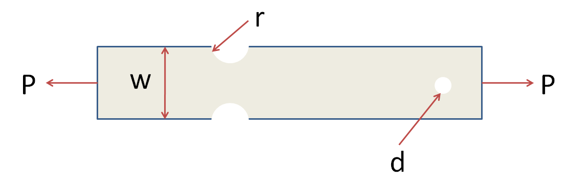
Click here to see an enlarged image
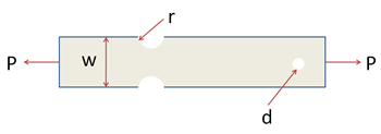
Consider the bar above. It is 10 inches long, 3 inches wide (w) and 0.4 inches thick. The groove radius r is .5 inches, and the diameter d of the hole is .3 inches. The applied traction is 10,000 psi. The plate is made of A514 steel with a modulus of elasticity of 29e6 and a Poisson ratio of 0.3. Assume plane stress conditions are valid.
You can download our linear elasticity solution in ANSYS by clicking here. Unzip the file and load the solution into ANSYS Workbench as in the tutorial. Double-click on Results in Workbench to bring up the FEA results that have been calculated already. Note that our ANSYS solution makes use of symmetry and models the top half of the bar. You might need to change the units for the results display by selecting Units > US Customary (in, lbm, lbf, F, s, V, A).
1. Look at the deformation plot. From this plot, deduce the boundary conditions (displacement constraints and traction) that have been applied to this model.
2. Does the deformation variation look right? Why or why not?
Consider the stress components in a polar coordinate system (r,theta) centered at the right hole. These stress components are included in the results provided to you.
3. Does the Sigma-r variation look right near and away from the right hole? Why or why not?
4. Does the Sigma-theta variation look right near and away from the right hole? Why or why not?
5. Does the Tau-r-theta variation look right near and away from the right hole? Why or why not?
6. From the above 5 items, can you tell if the ANSYS model provided to you has been set up correctly? If there is an error in the set up, what might it be?